5 Information About the Sensor
Each configured sensor, in scan direction, has defined 3D areas within
which a measuring object can be scanned. In the following, such a 3D area
is called “measuring volume” (MV).
5.1 Sensor Configurations
Measuring Areas T-SCAN hawk
Measuring Mode Blue Lasers Red Lasers Photogram‐
metry
Suggested max. part size
[mm]
300 1000 4000
Measuring area in the center
of the measuring volume (L x
W) [mm]
170 x 170 410 x 350 1200 x 900
Average distance between
reference points [mm]
50 120 120
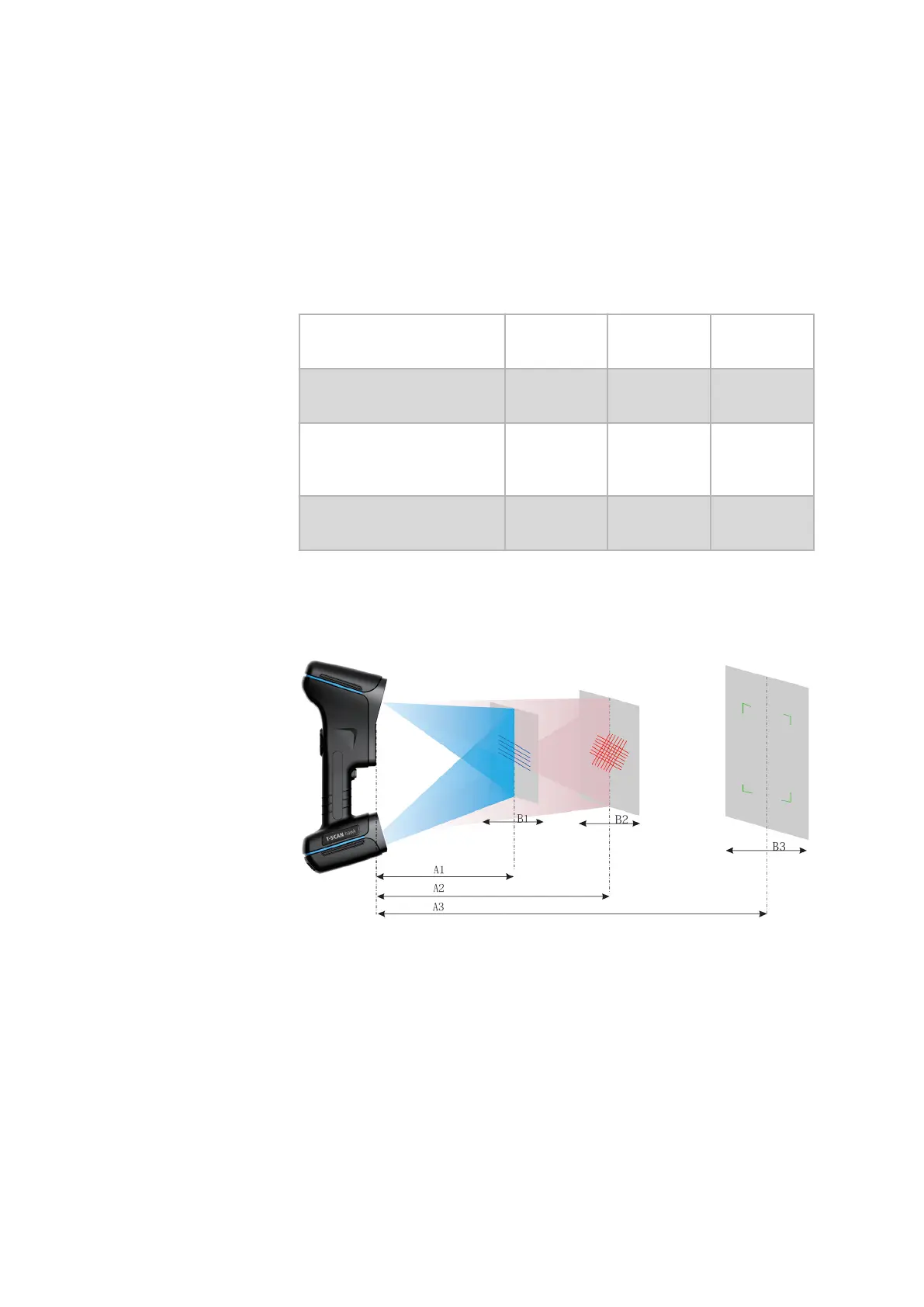
The measuring distance for the T-SCAN hawk depends on the preferred
resolution and the measuring mode.
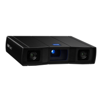
With the T-SCAN hawk, you can choose from dierent measuring modes.
This results in dierent measuring volumes.
Fig. 2: T-SCAN hawk measuring volumes, incl. photogrammetry measuring
area
0000001879_002_EN_30-09-2020 Page 10 (19)
 Loading...