CM151 3-6 CA - SERVICING
VIDEO DETECTOR
If there is no viewable picture on screen, access the
Service Menu and check default settings for the
following items:
Tune in a good off air signal. Place a high impedance
meter at pin 44 of ICX2200. Adjust to 2.5 volts DC.
AGC DELAY
With a strong noise free antenna signal, adjust ITEM
therefore RIF AGC on the Service Menu to a lower settings
until signal gets noisier. Increase settings for a noise
free picture.
Note: If settings goes to high above 50, the tuner
input will overload . Under certain conditions,
beats will also occur in the picture .
AUDIO DETECTOR
If no audio is present, access the Service Menu and
check default settings for the following items:
Tune in a good strong off air signal.
Place a high impedance meter on pin 54 of ICX2200 or
from + side of capacitor C1 214. Adjust Ll 202 for 4
volts DC.
MTS AND STEREO DECODER ALIGNMENT
The purpose of this procedure is adjusting registers of
SONY audio decoder and processor CXA2054S for MTS
models or audio decoder CXA2104S for STEREO models(I
1400 in both cases).
Note: Alignment should be accomplished at least ten
minutes after the TV set had been turned on.
Five register of the audio processor should be adjusted
for MTS models and three for STEREO models. Bits TEST-
DA and TEST1 should be set according with the current
adjust for MTS models (for STEREO models bits TEST-DA
and TEST1 will not be shown on the service menu because
their status do not need to be changed to do the
adjustments).
Inside of the service menu (only for MTS models):
Both TEST-DA = “0" and TESTI = “0" conditions are
selected when the internal menu is activated.
Enter the “SWAP” key of the remote control, then ten
bits registers will display in the bottom of the screen
(see the figure 1). The first one is TESTDA register and
the second one is TEST1 register.
Enter the “QUIT” key of the remote control in order to
set TESTDA = “0” and TEST1 = “1”.
Enter again the “QUIT” of the remote control in order
to invert the state of the registers.
AATT Adjust
(for MTS and Stereo models)
Set bits TEST-DA = “0” and TEST1 = ‘0" of IC1400.
Set the chassis for RF input.
Input signal: PIF 30 dBmv modulated with color bars at
85% mod., SIF 19 dBmv modulated with 100 Hz at 25
KHz deviation (100 % mod.), 75 us off.
IF AND AUDIO ALIGNMENT PROCEDURE
MICRO LOCATION RANGE PRESET VALUE
221-01384 17 0-63 42
221-01385 17 0-63 42
221-01386 17 0-63 42
221-01387 16 0-63 42
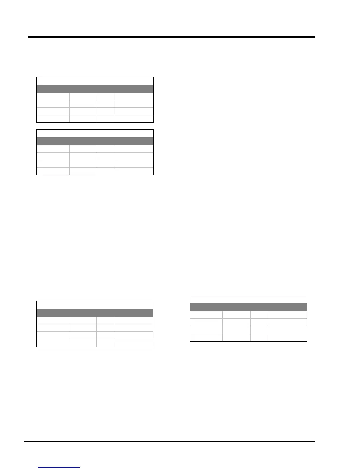
RFAGC
MICRO LOCATION RANGE PRESET VALUE
221-01384 21 0-127 52
221-01385 21 0-127 52
221-01386 21 0-127 52
221-01387 21 0-127 52
PIFVCO
MICRO LOCATION RANGE PRESET VALUE
221-01384 16 0-63 46
221-01385 16 0-63 46
221-01386 16 0-63 46
221-01387 16 0-63 46
AUD LVL
MICRO LOCATION RANGE PRESET VALUE
221-01384 32 0-15 9
221-01385 29 0-15 9
221-01386 29 0-15 9
221-01387 26 0-15 9
A ATT