SR23 - 923-03509 1-5 CS - GENERAL
USING PCZTV
Once the connections to the receiver monitor have been
completed, the receiver/monitor can be used to view
images from the computer.
1. Turn on the receiver/monitor
2. Tune the receiver/monitor to the appropriate source.
3. Turn on the computer.
4. The computer images should be visible on the screen.
VIDEO ADJUSTMENT
Adjustments to the computer video image are controlled
through the remote control. The 2 and 8 buttons shift
the display vertically. The 4 and 6 buttons shift the dis-
play horizontally. 1 is Zoom, 0 is freeze, and 5 gives
menu access.
CONNECTIONS
RECORDING THE COMPUTER IMAGE
If your VCR has an video input jack, the computer im-
ages can be recorded to video tape. Connect the VCR as
described by the illustration on the previous page.
This jack pack provides L/R audio input paired with com-
puter data input which will allow recording of audio
along with the video images. Your computer must pro-
vide audio out that can be connected to the jack pack
input on the receiver/monitor.
CHOOSING A DESKTOP PATTERN
Because of a television’s low resolution (as compared to
that of a computer monitor), avoid using computer desk-
top patterns that consist of elaborate designs or colors.
These can tend to vibrate or distort on the screen.
The recommended desktop pattern is either Black, a lim-
ited gray design, or some other solid dark color.
VIDEO DISTRIBUTION AMPLIFIER
If your receiver/monitor will be part of a closed circuit
network using a cable that is longer then 25 feet, or if
several sets will be used together using the loop out
jack, then a video distribution amplifier will probably
be necessary to ensure adequate signal strength is pro-
vided. These types of amplifiers can be purchased sepa-
rately in many consumer audio/video stores.
Pin Connection Pin Connection
1 Red Video Input 9 No Connection
2 Green video Input 10 Digital/Sync (mode)
3 Blue Video Input 11 Reserved (mode)
4 Reserved 12 No Connection
5 Reserved (test) 13 Horizontal Sync
6 Red Video Ground 14 Vertical Sync
7 Green Video Ground 15 No Connection
8 Blue Video Ground
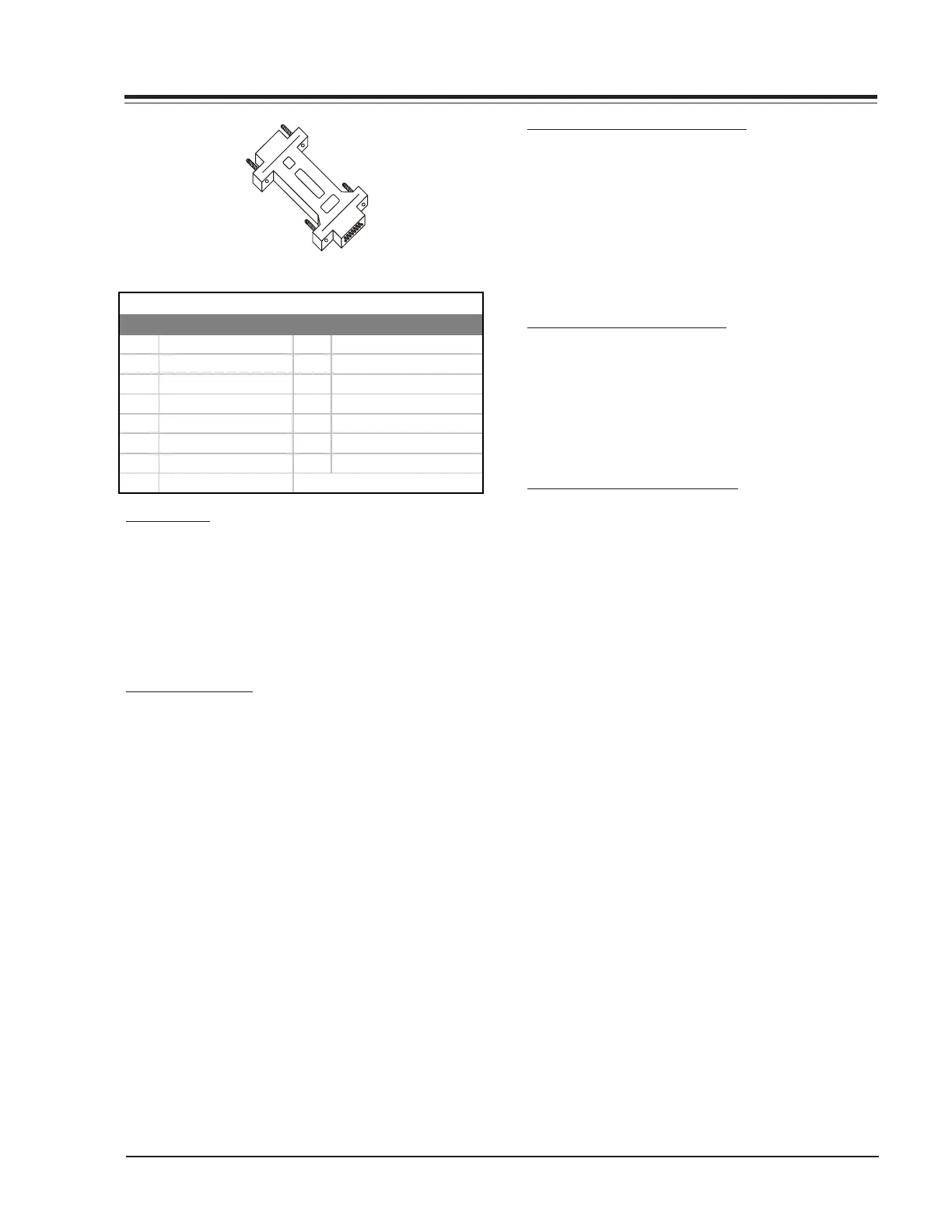
DB15 Pin Descriptions
HD DB15
(15 pins aligned
in three rows)
DB15
(15 pins aligne
in two rows)
HD DB15 Femal to DB15 Male Ada
ter