SR23 - 923-03509 3-1 CS - SERVICING
CIRCUIT OVERVIEW
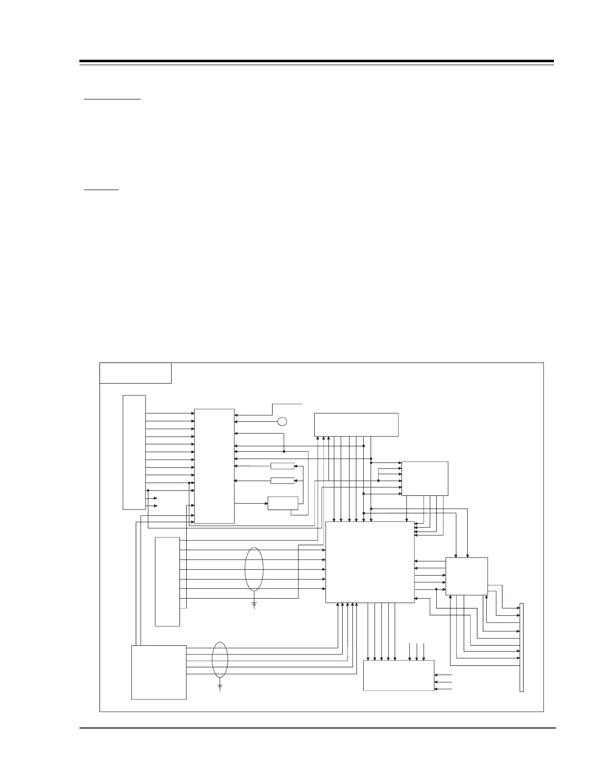
CHASSIS OVERVIEW
CONNECTIONS
This chassis has two means of A/V connectivity, one
jackpack in the front and one in the back. The rear
jackpack accommodates composite video, Y/C (super
video), RGB Computer, and TV RF inputs. The front
jackpack has only composite video and RGB computer
inputs.
SIGNALS
Two types of signals, NTSC and SVGA, are processed in
the set. NTSC signals enter by four inputs.
• CV RF: The IF section sends the composite
video to the A/V switch (ICX2900) at pin 53
(VinE4).
• CV-1: Fed from the rear jackpack to the A/V
switch at input pin 7 (VinS1).
• CV-4: This input, called Camport, is fed to the
A/V switch via pin 5 (VinE1).
• Y1-IN: This is the luminance input of the Y/C
(super video) connector and is fed to the A/V
switch through pin 15 (YinS2).
• C1-IN: This is the Chroma part of the Y/C (super
video) connector and is fed to the A/V switch
through pin 17 (CinS2).
All of these signals must be input to the A/V switch
with a 1 Volt Peak-to-Peak (Vp-p) level. The
microprocessor selects the signal through the I
2
C bus.
If the signal is composite video, it is sent to the comb
filter to separate the luminance and chroma components.
The luminance signal is fed back to the A/V switch at
pins 9 (YinS1) and 48 (Yin1). The chroma signal is sent
to a pair of band-pass filters, one for the composite
video inputs and one for the COMPOSITE VIDEO RF
(because the two signals have different levels). Then
the chroma is fed back to the A/V switch via pins 11
(CinS1) and 40 (Cin1).
The correct signal is selected by the microprocessor
and the A/V switch sends it to pins 44 (Yout1) and 42
(Cout1) and to ICX2201.
221-01053
CV-1
L1-IN
R1-IN
L2-IN
R2-IN
Y1-IN
C1-IN
L3-IN
R3-IN
Y MON OUT
C MON OUT
VM-OUT L
VM-OUT R
RESET
R
G
B
HS
VS
CV SEN
CV IN
Y IN
C IN
C OUT
Y OUT
R
G
B
HS
VS
CV RF
Y INS1
Y IN1
C INS1
C IN1
V OUT
SCL
S
D
A
S
C
L
BGF
B
SDA
COMB FILTER
BPF
BPS
C OUT
Y OUT
C IN
Y IN
SCL
HS
VS
SDA
9V
IC6000
221-01391-P07
ICX2200
221-01376
ICX2600
221-01378
TV
One
Card
Front
Jack
Pack
Rear
Jack
Pack
ICX2201
221-01377
ICX2900
Video Circuit
6V
FIL
R
SECTION 3
CIRCUIT OVERVIEW