SR24 - 923-03509 ii CS - SAFETY
PRODUCT SAFETY SERVICING GUIDELINES FOR AUDIO-VIDEO PRODUCTS
X-RADIATION
To prevent possible exposure to radiation caused by excessive
CRT Anode voltage, the CS Chassis incorporates a “High Volt-
age Shutdown” circuit. This circuit senses the level of flyback
pulse from the “Flyback Transformer” representative of the
actual high voltage on the CRT anode. When this level ex-
ceeds a predetermined voltage, the circuit shuts down the
horizontal drive, preventing further generation of anode volt-
age. In this condition, the horizontal drive is “latched” off for
about 5 seconds, after which, restart is attempted.
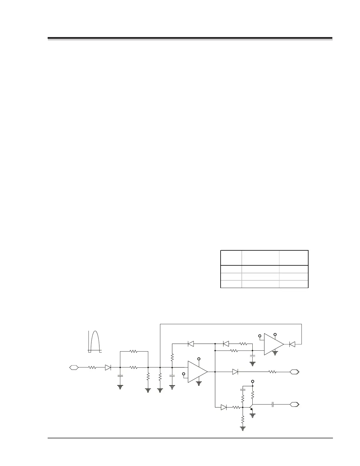
SHUTDOWN CIRCUIT OPERATION
The flyback pulse voltage from Pin 6 of TX3201 (Flyback Trans-
former) is peak detected (rectified) by the action of diode
D3206 and capacitor C3214. This forms a DC voltage appear-
ing on C3214 representative of the CRT anode voltage (HV)
produced by T3201. This voltage is divided down by precision
resistors RX3214, RX3215, RX3216 & RX3217. This lower volt-
age, appear on the non-inverted input (pin 5) of IC3201.
If the CRT anode voltage become excessive, pin 5 of IC3201
will be higher than inverted input of pin 6. This will cause the
output of pin 7 to rise to approximately 15 volts. This signal
(SD_DRV) is sent to the base of Q4000 causing Horizontal
Drive to be disabled and latched, which causes the HV to
shutdown. In about 5 seconds, the shutdown circuit resets
(Pins 8, 9 & 14 of IC2900), the Horizontal Drive and HV will be
reestablished. The circuit formed by Q2907, C2913, C2916,
D2908, R2923, R2935, R2936, and R2937 disables the HV
compensation output (Q2902-b signal) during turn on and shut-
down conditions (transients).
CRT ANODE HIGH VOLTAGE MEASUREMENT PROCEDURE
Each CRT screen has it’s own safe operating Anode Voltage
and shutdown voltage. Critical Safety components (designated
with an ‘X’ in the component designator) are designed to
operate the CRT at a safe operating Anode voltage and pro-
vide proper shutdown thresholds. If replacement of any of
these components is deemed necessary, it is important to use
original type Zenith replacement components.
After a replacement is made, confirm proper Anode voltage
using the following procedure.
Measurement of the CRT Anode voltage must be performed
with no visible raster on the screen and operating at nominal
horizontal scanning frequency 15.734 or 37.9 Khz (TV or SVGA
signal).
After discharging the CRT, connect a high impedance high
voltage meter to the CRT anode. Turn the television ‘On’ and
confirm good signal is being displayed. Reduce Brightness
and Contrast settings until the picture is well extinguished.
Observe the Anode voltage meter reading and compare with
the table below for the proper CRT screen size. If the voltage
reading is higher than the maximum, verify circuit component
values and proper operation.
HV SHUTDOWN MEASUREMENT PROCEDURE
1. Adjust the beam current to 0 mA in NTSC mode.
2. Apply a variable DC voltage to pin 10 of the PTD1 connec-
tor, from 20 to 0 Vdc, starting at 20 Vdc.
3. Slowly decrease supply towards zero.
4. Remove DC voltage from pin 10 of PTD1.
5. After approximately 5 seconds, verify that the HV is rees-
tablished (High Voltage Reset).
SHUTDOWN SAFETY CIRCUIT
IN
RX3213
From Pin 6, T3201
D3206
C3214
RX3216
RX3217
C3215
RX3214
RX3215
R3221
D3207
+15V
+5V
V-
V+
+
-
IC3201
R4015
OUT
To Base of Q2902
SHUTDOWN
(SD_DRV)
Flyback Pulse
+15V
V-
V+
+
-
IC2900
8
+15V
OUT
C2913
R2923
R2935
C2916
Q2907
R2936
R2937
D2908
D4002
C2917
R2943
R2944
D2909
D2910
To Base of Q4000
HV COMPENSATIO
DISABLE
+5V
9
14
Screen
Size
HV Nominal
Level (kV)
HV Max
Level (kV)
27" 27 29
32" 30 31.5
36" 30 31.5