SERVICE MENU (continued)
SR23 - 923-03509 2-5 CS - SERVICE MENUS
90 Cr offset1: For canceling the offset between CrCb of
IN1 and SELIN systems. Range: 0-15, 0 = -10 mV, 7 =
0 mV, 15 = +12 mV. This variable range is DC variation
amount of respective input pins.
91 Cb offset1: For canceling the offset between CrCb of
IN1 and SELIN systems. Range: 0-15, 0 = -10 mV, 7 =
0 mV, 15 = +12 mV. This variable range is DC variation
amount of respective input pins.
92 Cr offset2: For canceling the offset between CrCb of
IN1 and EXT systems. Range: 0-15, 0 = -10 mV, 7 = 0
mV, 15 = +12 mV. This variable range is DC variation
amount of respective input pins.
93 Cb offset2: For canceling the offset between CrCb of
IN1 and EXT systems. Range: 0-15, 0 = -10 mV, 7 = 0
mV, 15 = +12 mV. This variable range is DC variation
amount of respective input pins.
94 Sub-Con: Contrast gain control (Y system level ad-
justment). Range: 0-15, 0 = -1.9 dB, 7 = 0 dB, 1 5
= +1.7 dB.
95 Sub-Col: Color gain control. Range: 0-63, 0 = -2.1dB,
7 = 0 dB, 15 = +1.8 dB.
96 Sub-Hue: Tint center control. Range: 0-63, 0 = -8
degrees (Flesh color appears red), 8 = CENTER, 15 = +8
degrees (Flesh color appears green).
97 Cti-Level: Color difference signal edge enhancement
setting. Range 0-3, 0 = OFF, 1 = Low, 2 = Medium, 3 =
High.
98 R-Y/R: R-Y axis +(R-Y) component setting. Range: 0-
15, 0 = Maximum, 15 = Minimum.
99 R-Y/B: R-Y axis -(B-Y) component setting. Range: 0-
15, 0 = Maximum, 15 = Minimum.
100 G-Y/R: G-Y axis -(R-Y) component setting. Range:
0-15, 0 = Maximum, 15 = Minimum.
101 G-Y/B: G-Y axis -(B-Y) component setting. Range:
0-15, 0 = Maximum, 15 = Minimum.
102 Lrgb2-Level: LRGB2 system picture level control.
Range: 0-15, 0 = -5 dB, 15 = 0 dB.
103 Gamma: Control of gamma correction amount. 0 =
OFF. 15 = MAX (output increased by 15 IRE at input
40 IRE point).
104 Pabl-Level: Setting of level detection DC at RGB-
OUT of PEAK-ABL. 0 = Level detection DC : 4.9 V. 15 =
Level detection DC : 6.8 V.
105 Blk-Bottom: RGB-OUT bottom limiter level control
(valid when BLKSW = 1). The limiter level is replaced
with the reference DC for each H in RGB system, and it
is defined by the drop voltage from that DC; it is not
dependent on DC level control setting made by BRIGHT,
etc. This limiter functions for all video signals. For
further details, refer to the description of operation.
Range: 0-15, 0 = Limiter level: -1.25 V, 15 = Limiter
level: -0.65 V.
106 Sub-Shp: Sharpness center control (when SYSTEM =
0, SHARPNESS = 31, SHP-f0=1). Range: 0-3, 0 = 0 dB,
3 = + 4 dB.
107 Shp-F0: Sharpness f0 setting (automatically set to
f0 best suited to each system). Range:0-1.
108 Pre/Over: Preshoot to overshoot ratio setting.
Range: 0-3, 0 = PRE : OVER 1:1.3, 3 = PRE : OVER 3:1.
109 Lti-Level: Luminance signal edge enhancement set-
ting. Range: 0-3, 0 = OFF, 1 = Low, 2 = Medium, 3 =
High.
110 Dc-Tran: Y system DC transmission ratio setting.
Range: 0-1, 0 = 100%, 1 = 77%. These variable range
is the case when SCP clamp pulse duty is 4%.
111 D-Pic: Dynamic picture (black expansion) control.
Range: 0-3, 0 = OFF, 1 = Low: inflection point 30 IRE,
2 = Medium: inflection point 35 IRE, 3 = High: inflec-
tion point 40 IRE.
NTSC IC 221-1378 FROM 112 TO 157
112 Not Used
113 Left_Blk: HBLK width control for left side of picture
when HBLK_SW=0. Range 0-63, Initial value: 31.
114 Afc_Range: AFC pull-in range setting (100% Free-
running frequency). Range: 0-1, Fixed Value: 0.
115 Fh_Sw: Horizontal Drive frequency range. Range: 0-
1, Value: 0 for 15.75 KHz, NTSC mode, 1 for 37.9 KHz,
Monitor mode.
116 Right_Blk: HBLK width control. Range: 0-63, Initial
value: 31.
117 Afc_Mode: AFC loop gain control. Initial value: 31.
118 Clp: Clamp pulse phase setting. Range: 0-15, Initial
value: 0.
SELH-OUT Clamping Pulse Generation Block
0 = THROUGH 0 = 1.4 us
1 = 1.4 us 1 = 1.4 us
2 = 1.7 us 2 = 1.7 us
3 = 3.7 us 3 = 3.7 us
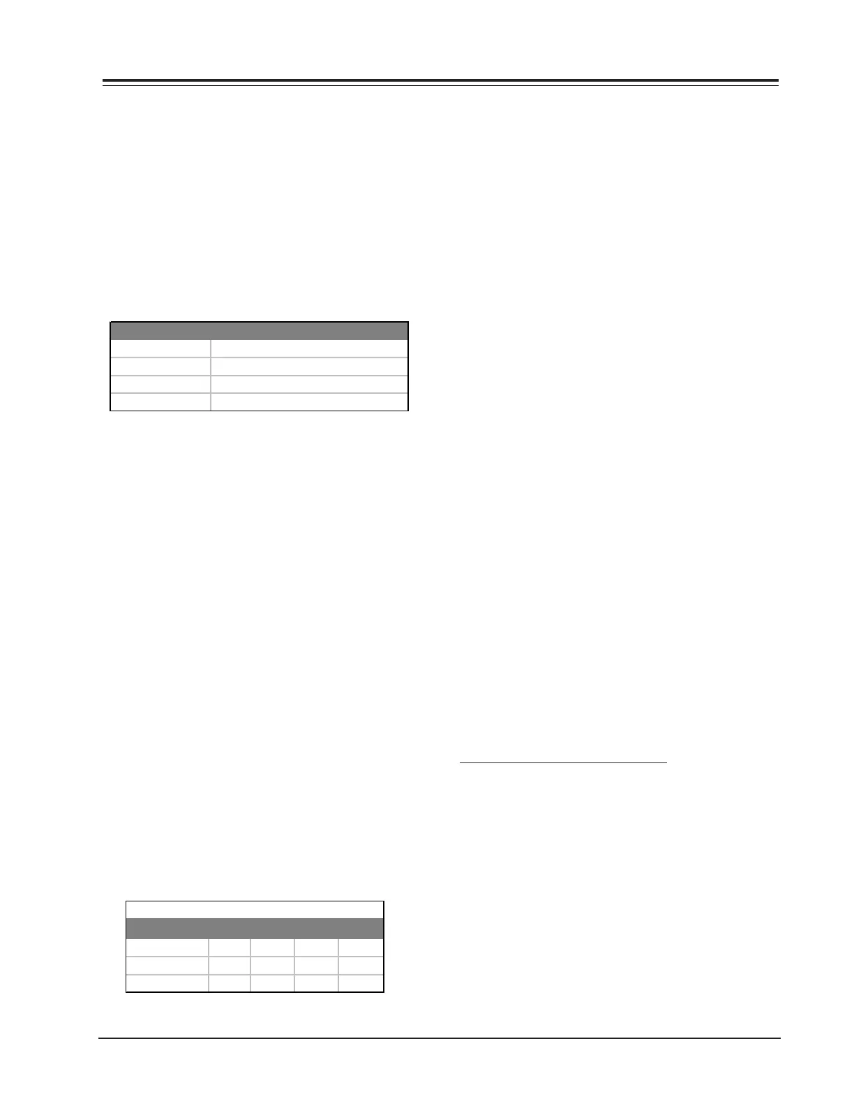
R-Y/R R-Y/B G-Y/R G-Y/B
NTSC-JAPAN
612105
NTSC-USA
7288
PAL/SECAM
13 15 8 4
Detection Axis Standard Values