SR23 - 923-03509 3-7 CS - SERVICING
CIRCUIT OVERVIEW (continued)
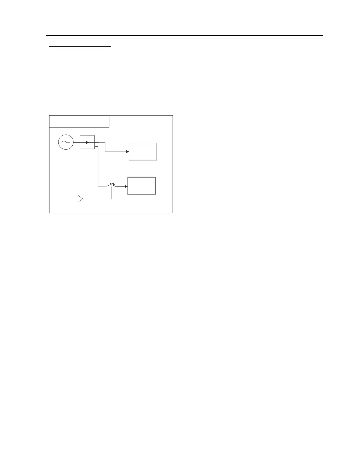
SWITCH MODE REGULATOR
This chassis has a switching power supply (quasi-
resonant topology type). The AC line is routed through
the fuse FX3400 (4A @ 250 V fast blow) and then
through the bridge rectifier circuit BR3400 and CX3407.
The AC operation range is between 90 Vrms to 135 Vrms.
A filter consisting of LX3400 and CX3401 is employed
before the rectifier circuit to reduce noise from the AC
line and vice versa (EMI).
Switch Mode Regulator
Stand By
Power Supply
Switched
Power Supply
Power
Control
AC
Line
The voltage output of the rectifier (150VDC) is supplied
to the Main Switch Mode Regulator Power Supply (SMPS)
& Standby Switch Mode Regulation Power Supply. Its
output should be operating in the range of 127.3 VDC
to 190.9 VDC.
The Main SMPS consists of ICX3400, ICX3401, and
ICX3402. Its chopper transformer consists of TX3400
and the standby SMPS. The standby SMPS consists of
ICX3406, ICX3407, ICX3408, and the standby chopper
transformer TX3401.
STAND-BY START UP
When the PIN 4 of ICX3406 terminal voltage reaches 16
VDC (typical), the control circuit enables regulator
operation. Once the regulator output voltage is
established, the drive winding DX3415 starts to charge
CX3430 via DX3415. The voltage on CX3430 thus recovers
to the nominal drive voltage.