Cleaning Procedure
WARNING: Be sure that the monitor's power cable
is
unplugged before cleaning.
•
•
•
Clean the cabinet with a lint-free cloth, lightly
dampened with a mild cleaning solution. Do
not
spray liquids directly on the monitor or use a wet,
saturated cloth.
Clean the screen with a good quality glass
cleaner.
Be
sure that the monitor is completely dry before
applying electric power.
~
0
POIJER
SUPPLY
ASSEMBLY
AD1
CRT
SOCKET
BOARD
(SEE FIGURE
5-1
MONITOR
SCHEMATIC)
+150Y
G2
,
?
RGB
G2
rccus
SIGNALS
VOLTAGE
VDLTAGE
P403
F=1
P20~
P405
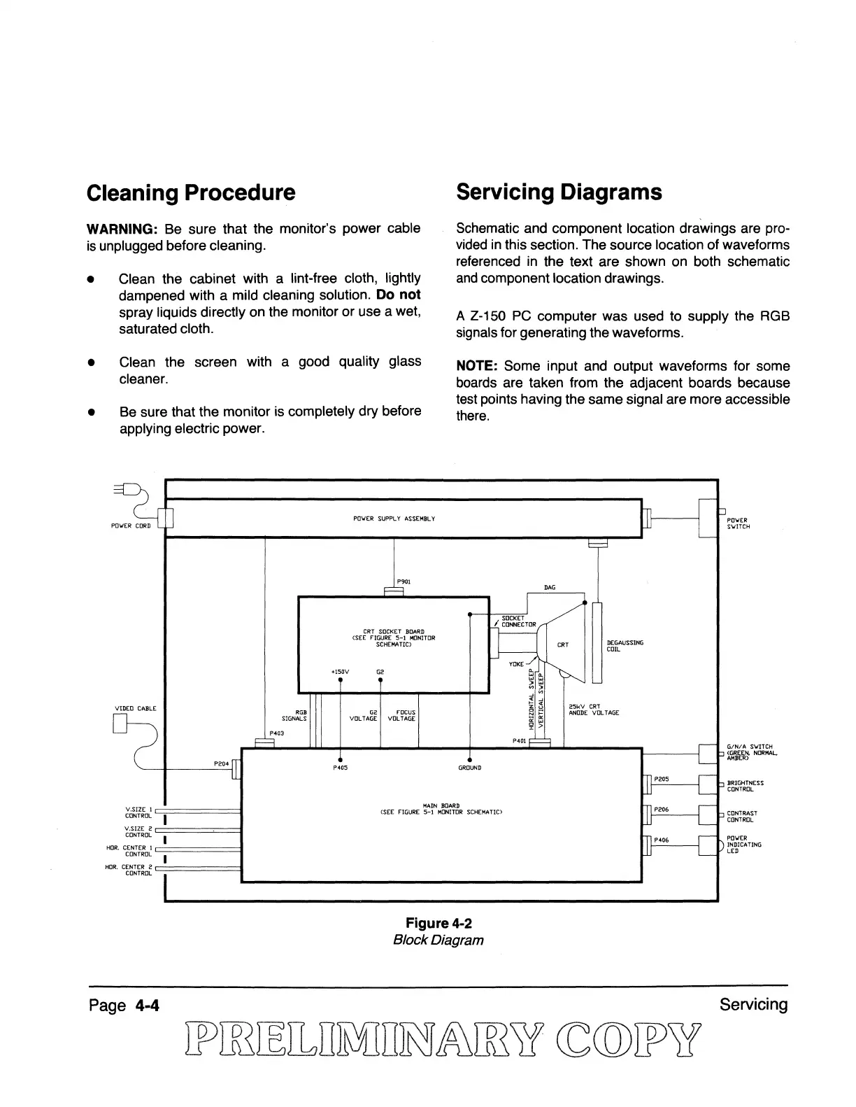
Servicing Diagrams
Schematic and component location drawings are pro-
vided
in
this section. The source location of waveforms
referenced
in
the text are shown on both schematic
and
component location drawings.
A Z-150
PC
computer was used to supply the RGB
signals for generating the waveforms.
NOTE: Some input and output waveforms for some
boards are taken from the adjacent boards because
test paints having the same signal are more accessible
there.
9
DAG
I
SOCKET
/
o
CONNECTOR
DEGAUSSlNG
CRT
COIL
YOKE-::t-~
...
"-
......
:>
...
"':>
-'
"
"
-'
>-
"
2SkY
CRT
z u
~
~
ANODE
VOLTAGE
«
...
'i' >
P4Dl
r===:J
GROUND
~P205
Jt
L
I"
L
S-"
L
POIJER
SIJITCH
GIN/A
S'lJITCH
~~tl~
NORMAL.
BRIGHTNESS
CONTROL
V.SIZE 1
MAIN
BOARD
]",0.
S-"
CONTROL
I
V,SIZE 2
CONTROL
I
HO
R.
CENTER
1
CONTROL
I
HO
R.
CENTER
2
CONTROl
Page
4-4
(SEE
FIGURE
5-1
M[JIIITDR SCHEMATIC)
Figure
4-2
Block Diagram
]P<"
L
I)
L
CONTRAST
CONTROL
POWER
INDICATING
LED
Servicing