19
!! IMPORTANT !!
The choice of the place of installa-
tion can be carried out only once. A
subsequentchangeisnotpossible.
The selection is being activated with
thedoorsymbol(toprightofthe
display):
■
Press and hold the button.
■
The door icon disappears and ap-
pearsaerabout2secondsagain.
■
Then release the button immedi-
ately.
The selected setting is accepted and
theunitisconguredforthechosen
place of installation. The chosen
place of installation can be checked
intherstdisplayoflevel3(Pt1000r
= return pipe resp. colder pipe / Pt
1000u = supply pipe resp. warmer
pipe).
The meter is now ready for operation.
Pulse inputs and outputs (optional)
By meters with pulse inputs, the
pulse value can be called up in the
display(seethedisplayoverview,
level4).Thepulsevalueofthe
outputs is permanently set and
corresponds with the last position of
the associated display value.
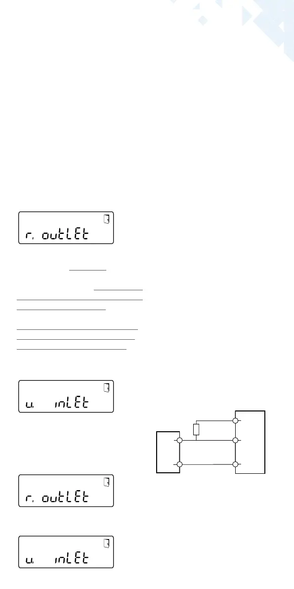
Typicalconnection(*)
(*)Theconnectionoftheexternal
resistor could be necessary to en-
sure an integrated current limiter.
Example:
Output 1 = energy output
Energy display = XXXXX.XXX
Last position = 0.001 MWh = 1 kWh
Output pulse = 1 kWh
U = 3 … 30 V
Imax = 20 mA*
GND
Pulse
V Out
white
yellow
green
brown
pulse
■
Fill in the putting into use report
in accordance with PTB-Directive
TRK9.
Note:
Only for versions with programma-
ble place of installation of the ow
sensor(marking“point of installa-
tion: see display” at the type plate
ontheside).
The meter is in the delivery status in
sleepmode(SLEEP1).
If the meter is being awakened from
the sleep mode, the following display
appears initially:
If the push button is not operated
within approx. 4 minutes, the me-
ter programs itself automatically
for installation in the return pipe of
the heating system (resp. pipe with
lower temperature level) and the
display shown above disappears.
For installation in the supply pipe
of the heating system (resp. pipe
with higher temperature level)
press the button shortly and the fol-
lowing display appears:
With a short button press you can
choose between the following two
displays.
Installation in return pipe:
Installation in supply pipe:

 Loading...