Do you have a question about the Zepro Z 150-155 and is the answer not in the manual?
Details the lift's electro-hydraulic system, components like cylinders, and the hydraulic unit.
Specifies crucial torque settings for mounting brackets and other installation points.
Provides detailed installation dimensions and tables for the Z/ZL 150/200/250-135 lift model.
Provides detailed installation dimensions and tables for the Z/ZL 150/200/250-155 lift model.
Provides detailed installation dimensions and tables for the Z/ZL 150/200-175 lift model.
Provides detailed installation dimensions and tables for the Z 150-195 lift model.
Provides detailed installation dimensions and tables for the Z 150/200/250 lift model.
Provides detailed installation dimensions and tables for the ZL 150/200/250 lift model.
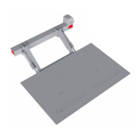
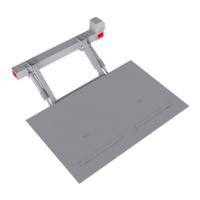
Details steps for preparing and installing the lift's support frame onto the vehicle chassis.
Schematic diagram illustrating the electrical and hydraulic connections for the Z/ZL-150/200/250 MA model.
Schematic diagram illustrating the electrical and hydraulic connections for the Z/ZL-150/200/250 DA model.
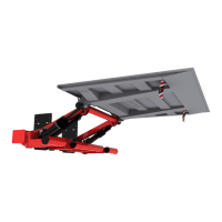
Diagram for MA model with hydraulic auto-tilt, showing system connections.
Explains the structure, identification, and interpretation of fault codes.
Details fault code resetting procedures and supply voltage tolerance.
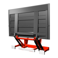
Instructions for mounting the lift platform onto the lift arms and tilt cylinders.
Procedure for conducting static load tests to verify lift capacity and integrity.
Procedure for conducting dynamic load tests with nominal and overload conditions.
Verification of critical safety functions, including alarms and interlocks.
| Brand | Zepro |
|---|---|
| Model | Z 150-155 |
| Category | Lifting Systems |
| Language | English |