Do you have a question about the Zepro Z 2500-130 Series and is the answer not in the manual?
| Capacity | 2500 kg |
|---|---|
| Maximum Load Capacity | 2500 kg |
| Lifting Height | 130 mm |
| Material | Steel |
| Safety Features | Overload protection, emergency stop |
| Control | Remote control |
Safety warnings regarding clearance for moving parts and tilt limitations.
Warning against attaching non-approved third-party equipment.
Safety warnings regarding platform installation and approved installation kits.
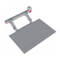
Steps involved in installing the support frame.
Steps for making electrical connections.
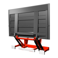
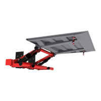
Steps for installing the platform.
Steps for installing the cylinders.
Definition of C dimension and its importance for installation.
Definition of D dimension and how it's obtained.
Definition of A dimension and its dependency on C dimension.
Definition of H dimension and its constraints.
Detailed steps for installing the support frame.
Instructions for routing and connecting the control power cable.
Guidelines for positioning control devices for safety and visibility.
Guidance on routing the main power cable safely.
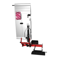
Installation steps for the underrun protection.
Requirements for underrun protection dimensions.
Procedures for checking, lubricating, and fitting the platform.
Schematic detailing functions, inputs, outputs, and controllers.
Schematic for MA model, config 14.
Schematic for DA model, config 16.
Details of fault codes and how they are displayed.
Procedure for static load testing (deformation and drift).
Procedures for dynamic load testing with max load and overload.
Checklist for testing all safety functions.
Specifies torque values for various assembly points.