Do you have a question about the Zepro Z 45-90 and is the answer not in the manual?
Explains warning symbols used in the manual for potential hazards.
Provides contact details for technical assistance and product number reference.
Lists and explains lift model identification codes.
States CE marking and compliance with EU Machinery Directive.
Confirms product meets relevant requirements according to EN 1756-1:2001 + A1:2008.
Specifies approved hydraulic oils and their types for replenishment.
Outlines requirements for a valid guarantee, including registration.
Advises against painting specific lift components to avoid damage.
Recommends battery disconnect for storage and charger use during operations.
Details clearance requirements for moving parts to prevent collision.
Prohibits connecting third-party equipment due to safety risks.
States rules for safe and approved lift installation.
Prohibits connecting third-party equipment due to safety risks.
Reinforces rules for safe and approved lift installation.
Outlines vehicle chassis requirements for tail lift mounting.
Specifies statutory dimensions for underrun protection.
Explains how to determine key installation dimensions (C, D, A, H).
Details how to make cut-outs in the rear beam for platform arms.
Explains temporary connection for testing functions.
Advises on battery charging during installation operations.
Shows how to connect control devices to the ZePRO1 card.
Shows how to connect control devices to the TLC-B1 relay card.
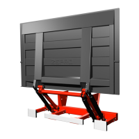
Overview and components of the hydraulic unit.
Instructions for removing transport strap and installing the hydraulic unit.
Details installing the support frame and mounting jig.
Explains fitting and fastening the chassis bracket.
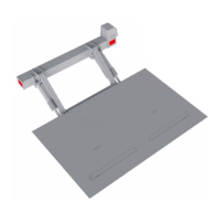
Instructions for fitting the lift platform to the arms.
Procedure for purging air from the hydraulic cylinders.
Mounting the angle sensor for autotilt function.
Mounting the angle sensor for 2-hand operation.
Mounting the IFM angle sensor for autotilt.
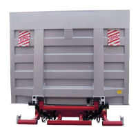
Specifies statutory dimensions and requirements for underrun protection.
Details the installation steps for underrun protection brackets.
Describes fastening aluminium profiles for underrun protection.
How to install and adjust arm stops.
Instructions for fitting horizontal sealing strip.
Instructions for fitting vertical sealing strips.
Instructions for fitting integrated rubber strip and arm stops.
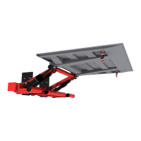
Guides on adjusting the tilt angle of the platform.
Explains the function of electric hose rupture valves as transport locks.
Guidelines for installing the primary and additional controllers.
Specifics on fitting Controller CD 1.
General principles for reliable cable routing and protection.
Recommends sizing electrical systems and cables correctly.
Provides electrical sizing for Z75 models.
Instructions for routing main power, earth cables, fuse, and switch.
Details mounting and connecting the main power switch.
Recommends installing an alarm for open platform status.
Instructions for routing the control power cable.
Guides on routing cables for warning lights and foot controllers.
Instructions for installing/adjusting cables in the cable grommet.
Steps for connecting controllers, lights, and alarms.
Procedure for tightening cable grommet screws after connection.
Shows connecting various control devices to the ZePRO1 card.
Shows connecting control devices and warning lights to TLC-B1 card.
Wiring diagram for warning lights and foot controls on TLC-B1.
Wiring diagram for warning lights and foot controls on ZePRO1.
Wiring for cabin switch and open platform alarm (TLC-B1).
Wiring for cabin switch and open platform alarm (ZePRO).
Electrical and hydraulic diagram for Z 45/75 (TLC-B1).
Electrical and hydraulic diagram for Z 45/75 (ZePRO1).
Diagram for Z 45/75 with electric Autotilt (TLC-B1).
Diagram for Z 45/75 with hydraulic autotilt (ZePRO1).
Lists lubrication points and recommended lubricant.
Procedure for checking and topping up hydraulic oil level.
Instructions for affixing load diagrams.
Guides on affixing the identification plate.
Placement instructions for the work area sticker.
Instructions for applying warning tape to platform edges.
How to affix controller stickers correctly.
Placement instructions for the danger area sticker.
Instructions for attaching warning flags.
Procedure for static load tests, including deformation and drift.
Procedures for dynamic load tests with max load and overload.
Dynamic load test procedure for specific load centers.
Lists safety functions to be tested.
Explains the process for registering the tail lift for warranty.
Lists weights of various lift components and platforms.
Specifies tightening torques for various installation points.
| Brand | Zepro |
|---|---|
| Model | Z 45-90 |
| Category | Lifting Systems |
| Language | English |