Do you have a question about the Zepro ZHZ 500-850 and is the answer not in the manual?
Explains warning markings and their significance.
Explains CE marking compliance and its importance for product safety.
Details recommended hydraulic fluids, including mineral and biodegradable types.
Explains how to interpret model identification codes for tail lifts.
Specifies components that must not be painted to avoid damage to seals and durability.
Instructions for replacing the transport plug with the standard tank cap.
Safety guidelines regarding clearances for moving parts and platform tilt angles.
Warns against attaching unauthorized equipment to prevent interference and risks.
General warning about installation requirements and potential risks.
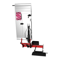
Details the steps involved in installing the primary support frame.
Provides instructions for making the necessary electrical connections.
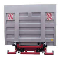
Describes the procedure for mounting and securing the lift platform.
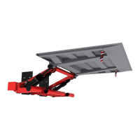
Details the steps for installing hydraulic cylinders.
Instructions for applying identification and warning decals.
Defines the C-dimension and its importance for lift placement.
Defines the D-dimension and its role in determining lift fit.
Defines the H-dimension and its relation to lifting height and ground clearance.
Specific steps for installing various vehicle-specific installation kits.
Steps for mounting and adjusting the lift unit to the chassis bracket.
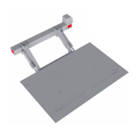
Describes the process of attaching and securing the lift platform to the arms.
Procedures for mounting and connecting the angle sensor for system feedback.
Instructions for mounting the hydraulic unit.
Guidelines for installing and positioning control units for safe operation.
Instructions for fitting and connecting the electrical junction box.
Guidance on routing and connecting the control power cable.
Procedures for routing and protecting the main power cable.
Instructions for connecting the license plate light to vehicle wiring.
Steps for attaching the connection ramp to the platform.
Instructions for adjusting the armstops for proper lift arm contact.
Description of the platform's automatic locking mechanism when folded.
Steps for adjusting the tilt cylinder for correct platform positioning.
Procedure for removing air from hydraulic cylinders to ensure proper function.
Explanation of the hydraulic locking mechanism for securing the platform during transport.
Diagram illustrating the MA connection to the main circuit board.
Diagram detailing the electrical connections for a 4-button control operation.
Diagram showing connections for cab switch and open platform alarm.
Illustrates various control device models and their connection points.
Illustrations showing the positions of different decals on the tail lift.
Explains the load capacity diagram decal and its interpretation.
Describes the information provided on the tail lift's identification plate.
Explains the decal indicating required clearance for safe operation.
Describes the decal providing operational instructions for the driver.
Explains the decal that marks the danger zone around the platform.
Describes the application and purpose of warning tape on platform edges.
Instructions for attaching warning flags to the top and edge of the platform.
Explains the meaning and guarantee provided by the CE marking.
Specifies which components should not be lubricated to prevent damage.
How to check and top up hydraulic fluid levels in the tank.
Steps for performing static load tests to check for deformation and drift.
Procedures for testing the lift with maximum load and overload conditions.
Checklist for verifying that all tail lift safety functions are operational.
Lists the weights of various lift components for lifting equipment selection.
Provides load centre data (TP1, TP2) for different load capacities and positions.
Details power requirements and recommended conductor sizes for safe operation.
Guidelines for battery care during storage and regular use to ensure longevity.
Shows the load capacity chart for the ZHZ 500 model.
Shows the load capacity chart for the ZHZ 600 model.
| Brand | Zepro |
|---|---|
| Model | ZHZ 500-850 |
| Category | Lifting Systems |
| Language | English |