Do you have a question about the Zepro ZHD 2500-150 and is the answer not in the manual?
Details important warnings and symbols used in installation instructions.
Explains the identification system for different models and specifications.
Advises against painting critical components like piston rods and hydraulic hoses.
Warns about collision risks with moving cylinders and specifies clearance requirements.
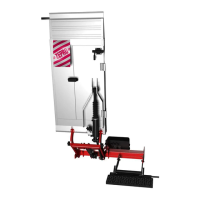
Outlines steps for installing the support frame, including jig use and chassis brackets.
Covers connecting control devices, cables, and the main power cable.
Defines C dimension as distance between support frame top and vehicle floor level.
Defines D dimension as space needed from rear edge of body to support frame front.
Detailed steps for mounting the support frame using a jig and chassis brackets.
Instructions for routing and connecting the control power cable from the cabin to the lift.
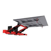
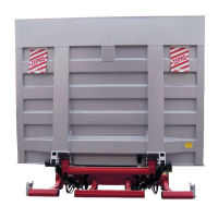
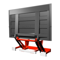
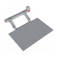
Steps for checking, lubricating, and fitting the platform to the arms.
Instructions for loosening bellows, adjusting tilt cylinders, and checking platform underhang.
Steps for connecting control devices, earth, and power to the control card.
Electrical and hydraulic schematic for the ZHD 2500 NN model.
Illustrates common control device models and their connections to the control card.
Function diagrams for ZHD 2500 MA model, Config 1, showing inputs, outputs, and illustrations.
Explains the fault codes displayed by the control card for troubleshooting.
Instructions for affixing load diagrams near the controller for visibility.
Details the information contained on the identification plate and its placement.
Lists lubrication points that require greasing on installation and periodically.
Instructions for checking and topping up hydraulic fluid levels.
Covers deformation and drift tests with static loads.
Checklist for verifying all safety functions are operational.
Lists the weights of various lift components and platform types.
Details power consumption and recommended cable sizes for 12V and 24V systems.
Lists specified torque values for various installation points.
| Brand | Zepro |
|---|---|
| Model | ZHD 2500-150 |
| Category | Lifting Systems |
| Language | English |