Do you have a question about the Zepro ZN 75-90 and is the answer not in the manual?
Highlights potential hazards and provides notes for understanding operations.
Ensures safe operation by maintaining clearance around moving parts.
Prohibits connecting third-party equipment to avoid system interference.
Safety warnings related to the installation process.
Specifies requirements for the vehicle chassis for tail lift mounting.
Details statutory dimensions for platform and underrun protection.
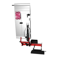
Overview and installation of the hydraulic unit.
Steps for measuring, positioning, and fitting the support frame.
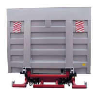
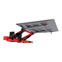
Instructions for fitting the lift platform to the arms.
Details statutory dimensions and installation of underrun protection.
Guidelines for installing the primary and additional controllers.
Ensures correct battery, charger, and cable sizing for the lift.
Installation of main power cable, earth, fuse, and main switch.
Wiring diagrams for connecting control devices to ZePRO1 card.
Wiring diagrams for connecting controllers to TLC-B1 relay card.
Procedures for performing static load tests, including deformation and drift checks.
Procedure for testing the lift with maximum load.
Procedure for testing the lift with 1.0x capacity load.
Checks for all safety functions to ensure proper operation.
Specifies tightening torque values for various installation steps.
| Brand | Zepro |
|---|---|
| Model | ZN 75-90 |
| Category | Lifting Systems |
| Language | English |