Do you have a question about the Zepro Z3NU 75-100 and is the answer not in the manual?
Details warning signs used in instructions for potential hazards and damage.
Ensures safe clearance around moving cylinders and platform tilt limits.
Prohibits connecting external equipment to prevent system interference and ensure safety.
Highlights safety requirements for installation, including ground level access and approved kits.
Specifies chassis requirements, including frame beam dimensions and moment of inertia for mounting.
Illustrates connections for control devices (CD15, CD1, CD2) to the ZePRO1 control card.
Shows connections for controllers (CD19, CD1, CD4) and warning lights to the TLC-B1 relay card.
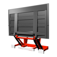
Instructions for mounting the lift to the vehicle chassis, including measurements and jig use.
Details on mounting the hydraulic unit onto the lifting frame for specific models.
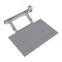
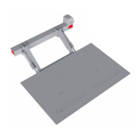
Steps for fitting the platform to the arms, lubricating bushings, and attaching tilt cylinders.
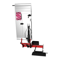
Instructions for installing the underrun protection, including bracket and aluminum profiles.
Guidelines for installing primary and additional controllers on the vehicle, considering traffic safety.
General principles for cable routing, emphasizing reliability, proper connections, and protection.
Guidance on sizing electrical systems, battery capacity, and cable cross-sections for reliability.
Procedure for installing main power, earth cables, fuse, and main switch, with options for different setups.
Instructions for mounting and connecting the main power switch, including drainage direction.
Diagrams for connecting control devices and warning lights to the TLC-B1 relay card.
Steps for connecting power, installing fuses, and activating switches to power up the tail lift.
Procedure for static load testing, including deformation and drift checks under load.
Details dynamic load testing procedures, including tests with max load and overload.
Checks to verify that all tail lift functions and safety features operate correctly.
| Brand | Zepro |
|---|---|
| Model | Z3NU 75-100 |
| Category | Lifting Systems |
| Language | English |