Do you have a question about the Zepro ZU 75-110 and is the answer not in the manual?
Contact info for technical help and advice on providing production numbers for correct information.
Safety advice regarding clearance for moving cylinders and platform tilt limits.
Warning against connecting third-party equipment due to interference with safety functions.
Warnings about platform ground level access and approved installation kits.
Reinforces prohibition of third-party equipment connection, citing risks of injury and damage.
Repeats warnings about platform ground clearance and approved assembly kits for safe installation.
Details chassis requirements for underrun protection and frame beam dimensions for structural integrity.
Specifies statutory dimensions for platform-to-underrun protection and ground clearance.
Explains how to calculate installation dimensions (C, D, A, H) for optimal lift placement.
Wiring instructions for connecting control devices to the ZePRO1 control card.
Wiring instructions for connecting control devices to the TLC-B1 relay card.
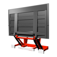
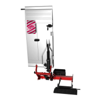
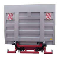
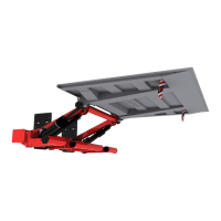
Overview and identification of the hydraulic unit components.
Steps for measuring, marking, and mounting the support frame using a jig.
Specifies statutory dimensions and requirements for underrun protection.
Detailed steps for installing the U-shaped protection brackets and fastening them.
Electrical and hydraulic schematic for Z 45/75 with TLC-B1 control system.
Electrical and hydraulic schematic for Z 45/75 with ZePRO1 control system.
Schematic for Z 45/75 with electric autotilt and TLC-B1 control system.
Schematic for Z 45/75 with hydraulic autotilt and ZePRO1 control system.
Procedures for static load testing, checking deformation, drift, and load capacities.
Procedures for dynamic load tests, including max load, overload, and different load centers.
Checklist for testing all safety functions of the tail lift.
| Brand | Zepro |
|---|---|
| Model | ZU 75-110 |
| Category | Lifting Systems |
| Language | English |