EasyManua.ls Logo

Zepro Z 250-155 User Manual

Default Icon
38 pages
To Next Page IconTo Next Page
Page #1 background imageLoading...
Page #1 background image
Z/ZL 150/200-135/155/175
Z/ZL 250-135/155
Sales
Mossvägen 8, 641 49 KATRINEHOLM, SWEDEN
Telephone: +46 150 - 489550
Telefax: +46 150 - 489551
E-mail: zepro@zepro.com
Internet: www.zepro.com
Factory
Allévägen 4, 840 73 BISPGÅRDEN, SWEDEN
Telephone: +46 696 - 17200
Telefax: +46 696 - 17242
E-mail: info@zepro.com
Internet: www.zepro.com
2016-09-06
54245TL
INSTALLATION INSTRUCTION
Z-LYFTEN PRODUKTION AB
Question and Answer IconNeed help?

Do you have a question about the Zepro Z 250-155 and is the answer not in the manual?

Zepro Z 250-155 Specifications

General IconGeneral
BrandZepro
ModelZ 250-155
CategoryLifting Systems
LanguageEnglish

Summary

CE Marking and Compliance

Installation Dimensions Overview

Additional Installation Dimensions

Support Frame Installation

Support Frame Preparation and Mounting

Guides on measuring, marking, and fixing the support frame to the vehicle.

Electrical System Installation

Control Unit Placement and Wiring

Instructions for positioning control units and routing cables.

Main Power Cable Connection

Details on connecting the main power cable to the starter motor and protection.

Electric and Hydraulic Diagram MA Models

MA Model Schematic Overview

Detailed schematic showing electrical and hydraulic connections for MA models.

Electric and Hydraulic Diagram DA Models

DA Model Schematic Overview

Detailed schematic showing electrical and hydraulic connections for DA models.

Electric and Hydraulic Diagram Auto-Tilt Models

Auto-Tilt Model Schematic Overview

Schematic for models with hydraulic auto-tilt function.

Connection Unit Overview

Connection Unit Information Codes

Connection Unit Fault Codes

Fault Code Identification and Meaning

Details fault codes, their identification letters, and associated meanings.

Fault Code Reset and Supply Voltage

Function Schemas and Signal Logic

MA Model Function Schema

Details signal inputs and outputs for MA models with auto-tilt.

DA Model Function Schema

Details signal inputs and outputs for DA models.

Bumper Bar Installation

Platform Installation

Platform Mounting and Axle Tightening

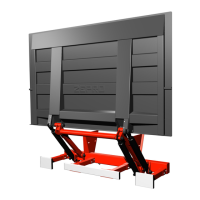
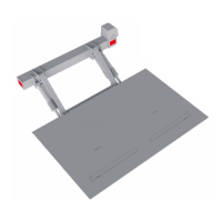
Guides on attaching the platform to lift arms and tightening bolts.

Lift Arm and Transport Lock Installation

Tilt Cylinder Adjustment

Maintenance and Lubrication

Tail Lift Load Testing Procedures

Static Loading Test and Deformation Check

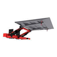
How to perform static load tests and check for permanent deformation.

Platform Deflection Test

Procedure for testing platform deflection under load.

Load Testing and Safety Checks

Dynamic Load Testing

Instructions for testing lift operation with nominal and overload conditions.

Tail Lift Safety Function Verification

Checks for safety functions like cabin switch, fuses, and warning lamps.

Related product manuals