Installation & Operation • 17
INSTALLATION & OpERATION
Door Leveling
On Crystal
™
coolers with same-swing doors, the door-to-door gap should be 3/8". On
Crystal
™
coolers with French-swing doors, there should be a 7/16" gap between doors
at the handle side and a 3/8" at the hinge side. To set the proper gaps, loosen the
screws holding the top or bottom door mounting plates, then shift the door.
BOTTOM MOUNTING PLATE
To move the bottom mounting plate, the center locking screw (located behind the
bumper) must be loosened.
1. To remove the bumper, use a athead screwdriver to pry it up from the bottom.
Lift the edge, and then slide the screwdriver down the entire length of the
bumper to loosen it. Once the bottom edge is disconnected, use a hammer to
tap the screwdriver upwards and disengage the bumper from the upper track.
Remove the bumper.
2. Loosen the center locking screw by 2 turns, accessed through the hole in the
bumper support plate (See Figure 20). This will allow the bottom mounting plate
to shift. Do not remove the center locking screw.
3. Tap the door’s aluminum extrusion with a rubber mallet to shift the door. Once
the door is in position, retighten the center locking screw.
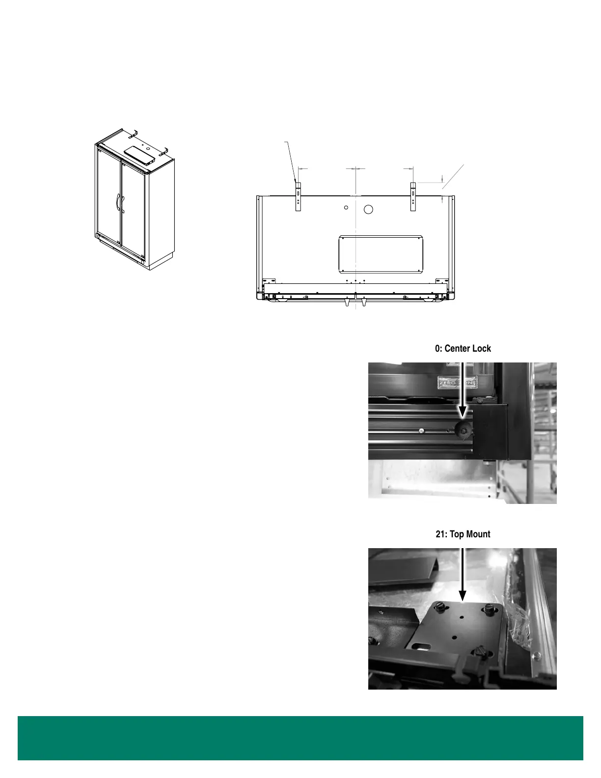
TOP MOUNTING PLATE
1. To access the top mounting plate, remove the top trim piece. This will require a
Phillips bit and a 1/4" hex screw bit.
2. Loosen all 3 screws that secure the slotted plate by 2 turns (See Figure 21). Do
not remove the screws.
3. Tap the door's aluminum extrusion with a rubber mallet to shift the door. Once
the door is in position, retighten all screws.
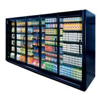
3" TO 5"
FROM REAR
OF CASE-
TO-WALL
5"-20" DIM
TO CENTER
5"-20" DIM
TO CENTER
SCREW (2) TIP OVER PREVENTION
BRACKETS (ZZ #18-0422)
TO TOP OF CASE AND TO
A SOUND STRUCTURAL
SUPPORT MEMBER IN WALL
TIPOVER PREVENTION BRACKET
ZERO ZONE WORKMANSHIP STANDARDS SHALL APPLY PER
ES-08-1007
ASME Y14.41-2012 & ASME Y14.5-2009 SHALL APPLY AS REQUIRED
ALL DIMENSIONS IN INCH UNLESS OTHERWISE SPECIFIED
RELEASED
SIGNIFICANT DIMENSIONS DENOTED BY
X.XX
OR
X.XXX
AND MUST MEET Cpk ≥ 1.33.
CRITICAL DIMENSIONS DENOTED BY
X.XX
OR
X.XXX
AND MUST MEET Cpk ≥ 1.66.
CAD DRAWING
NO MANUAL REVISIONS
COPYRIGHT INFORMATION
THIS DRAWING AND THE INFORMATION CONTAINED WITHIN,
IS THE SOLE PROPERTY OF ZERO ZONE, INC. ANY USE OF
THIS DOCUMENT OR DISCLOSURE OF ITS CONTENTS; BY
REPRODUCTION OR OTHER MEANS, WITHOUT THE WRITTEN
CONSENT OF ZERO ZONE, INC. IS STRICTLY PROHIBITED.
FINISH:
MATERIAL:
NOT TO SCALE
SCALE:
MODELED BY:
DRAWN BY:
4/24/2018
A
1 OF 1
66-0078
MOUNTING INSTRUCTIONS FOR
SHEET:
DATE:
REVISION
ZERO ZONE, INC.
110 NORTH OAKRIDGE DRIVE
NORTH PRAIRIE, WISCONSIN
USA 53153
DRAWING No:
DESCRIPTION:
REVISION INFORMATION
A
NEW ISSUE
12796
4/24/2018
AR
No.
REVISION DESCRIPTION
ECN No.
DATE
BY
Al Roeker
Al Roeker
SHEET SIZE
A
TOLERANCES SHALL APPLY
UNLESS OTHERWISE SPECIFIED
.X = ± .1 .XX = ± .02
.XXX = ± .005 ANGLES, ± 1º
FIGURE 19: Anchoring Ultra Narrow to a Wall
FIGURE 20: Center Locking Screw
FIGURE 21: Top Mounting Plate
 Loading...