Installation & Operation • 21
INSTALLATION & OpERATION
Rear Load Cases
Rear Load cases are shipped with the rear sliding doors removed and shipped
loose with the case. To maintain proper temperature, the Rear Load case must
be positioned in the opening of a walk-in cooler. Before attaching the cases to
the walk-in, measure the diagonal opening of the Rear Load case to ensure
a square case installation. If the diagonal measurements are not within 1/8",
the case must be re-leveled. After the cases are set, install the doors into the
opening by inserting the top of the door into the upper track and then sliding
the bottom of the door into the lower track.
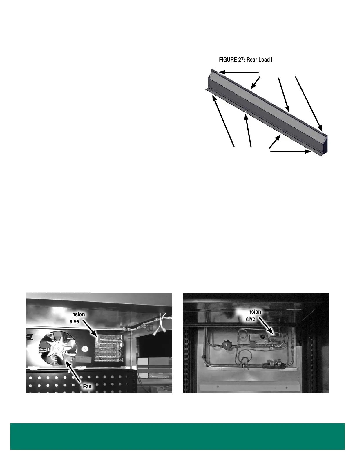
Rear Load cases may be ordered with an optional insulated close-off for
applications where a walk-in cooler does not have a curb along the oor (See
Figure 27). After the case is set, the close-off must be installed to the bottom
rear of the display case. It protects the display case from potential damage if a
pallet of food or beverages is smashed into the back of the display case. It also
prevents warm air from entering the walk-in cooler and prevents water from
owing underneath the display case.
Mechanical Components
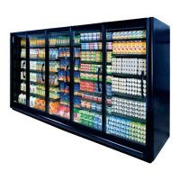
Air is circulated through the display case by fans. The fans are located above the false ceiling panel, and they can be accessed by removing the
screws holding the false ceiling panel. Air enters from the top front air grille, and air is discharged down the rear ducts (See Figure 28).
Typically, the expansion valve is located behind the false ceiling panel in the right-most door of each case. After removing the false ceiling panel,
you will see a rectangular cover panel. Remove the cover panel to access the expansion valve and suction line Schrader valve (See Figure 28).
Alternatively, the expansion valve may be located behind the optional right back duct per customer request. An access cover is provided in the
duct (See Figure 29).
Glycol cases typically have a balance valve located in the outlet line on the top of the case. If a stop solenoid is provided, it will also be located
in the outlet line on top of the case. Schrader taps are provided inside the case on the right-hand side of the coil for venting and draining the
system. An additional tap is provided on top of the case to allow for venting when the system is drained.
Expansion
Valve
Fan
FIGURE 28: Fan and Expansion Valve
FIGURE 27: Rear Load Insulated Close-Off
Fasten to Floor
Fasten to Case
FIGURE 29: Alternate Expansion Valve Location
Expansion
Valve