6 • Installation & Operation
INSTALLATION & OpERATION
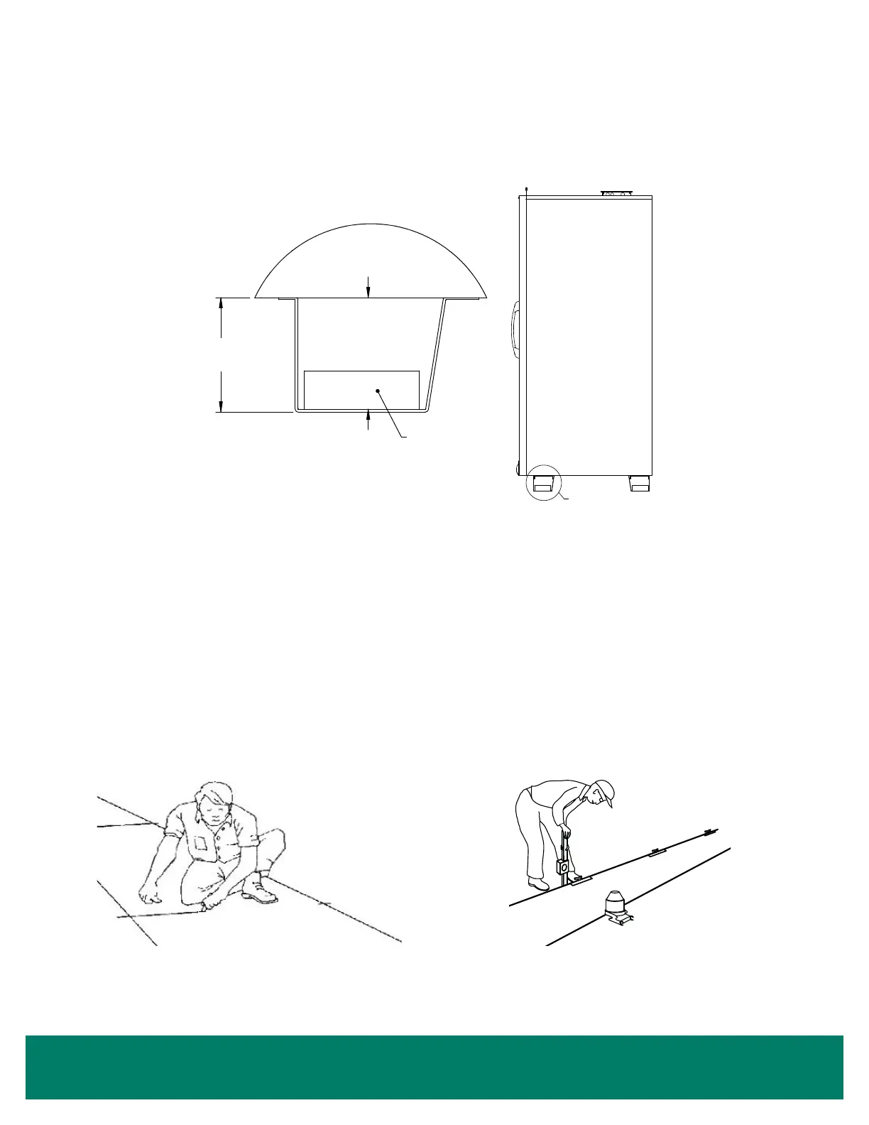
Spacer blocks are factory-installed in the end bases of 4 or 5-door cases that use bases taller than 3 1/2". These blocks limit the case's forward
tilt while it is being lifted by a forklift (See Figure 4).
Leveling
Cases should be set level from right to left to allow complete drainage of defrost and condensate water. Since a level oor area is seldom
available, the following steps are recommended to ensure a level installation. If your case uses seismic restraints, specic instructions for
attaching seismic restraints are included in your document package. Read and understand these instructions before assembling the lineup.
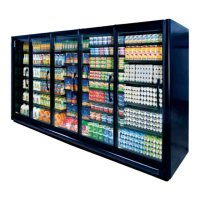
1. Measure off and mark on the oor the exact dimensions of the case lineup (See Figure 5). Refer to the xture plan or oor plan.
2. Snap a chalk line at the locations for the front and back positions of the bases.
3. Mark locations of all joints, both front and back.
4. Using a laser level or transit, nd the highest point along both base position lines. Using the high point as a reference, mark the difference
directly on the oor to each base, both front and back (See Figure 6).
5. If your case uses optional hat channel rails to raise the case height, place shims under the hat channel rails. On 3 and 4-door cases, hat
channel rails must be angled slightly to support the front and rear bases because the center bases themselves are not aligned (See Figure
7 through Figure 10 starting on Page 7).
FIGURE 4: Spacer Block
Spacer Block(s)
4 3/8" max. opening for
1, 2, and 3-door cases.
3 3/8" max. opening for
4 and 5-door cases.
FIGURE 5: Measure and Mark Exact Case Outline FIGURE 6: Mark Floor Level Difference