SET UP
Page5-27
03
- Normal, No Current when at Lock-up. Preset
for ZF220-550, 24VDC Systems.
04
- Normal, No Current when at Lock-up. Preset
for ZF2000, 24 VDC Systems.
05
- Inverse, No Current when at Lock-up. Preset
for ZF670, 1900 or 2500, 24VDC Systems.
06
- Preset for 12VDC ZF Hurth Systems.
07
- Preset for 24VDC ZF Hurth Systems.
The default val ue is
00
.
5-6.5.4.2 Function Code
L2
– Troll Minimum Pressure
This Function fine tunes the amount of current deliv-
ered to the proportional solenoid, so that clutch pres-
sure is at the minimum point where shaft rotations
are still possible.
The hydraulic pressure on the Clutch plate can typi-
cally be decreased to a point where the shaft is rotat-
ing at 30% to 50% of normal shaft RPM at Idle.
The available Values are
0.00
to
80.0
percent of t he
maximum current available. The Default Value is
10.0
%. The Value selected must always be at least
20% below or above (Normal/Inverted) the value
selected with Troll Maximum Pressure
L3
.
5-6.5.4.3 Function Code
L3
– Troll Maximum Pressure
This Function fine tunes the amount of current deliv-
ered to the proportional solenoid, so that clutch pres-
sure is at the maximum point prior to Clutch Plate
lock-up.
The hydraulic pressure on the Clutch plate can typi-
cally be decreased to a point where the shaft is rotat-
ing at approximately 70% of normal shaft RPM at
Idle. Attempts to increase pressure above this point
typically results in Clutch Plate lock-up.
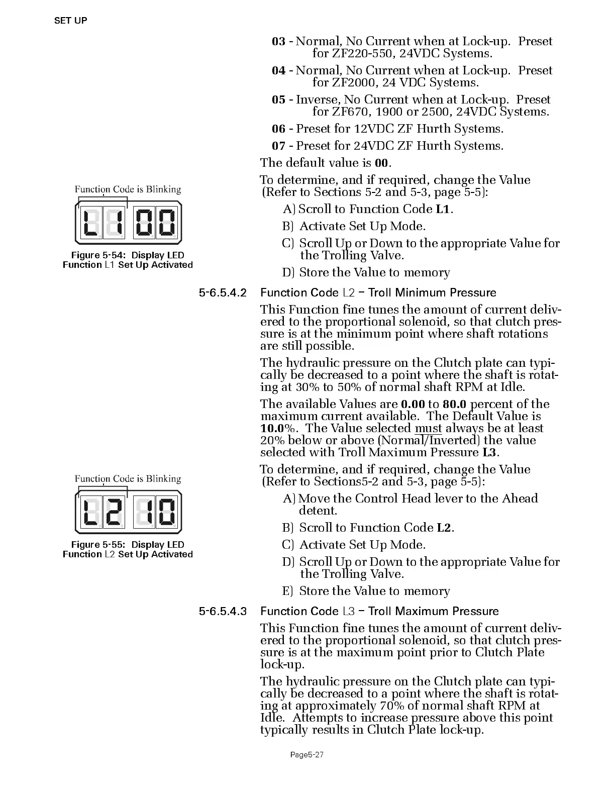
Figure 5-54: Display LED
Function
L1
Set Up Activat ed
To determine, and if required, change the Value
(Refer to Sect ions 5-2 and 5-3 , page 5-5):
A) Scroll to Function Code
L1
.
B) A cti v ate Set Up Mode.
C) Scroll Up or Dow n to the a ppropriate V alue for
the Trolling Valve.
D) Store the Value to memory
Figure 5-55: Display LED
Function
L2
Set Up Activat ed
To determine, and if required, change the Value
(Refer to Sect ions5-2 and 5-3, page 5-5):
A) Move the Control Head lever to the Ahead
detent.
B) Scroll to Function Code
L2
.
C) Acti v ate Set Up Mode.
D) Sc roll Up or Do wn to the a pprop riate V alue f or
the Trolling Valve.
E) Store the Value to memory

 Loading...