OPERATION
Page 2-18
2-16 P
LUGGABLE
C
ONNECTIONS
2-16.1 Standar d Pluggable Processor
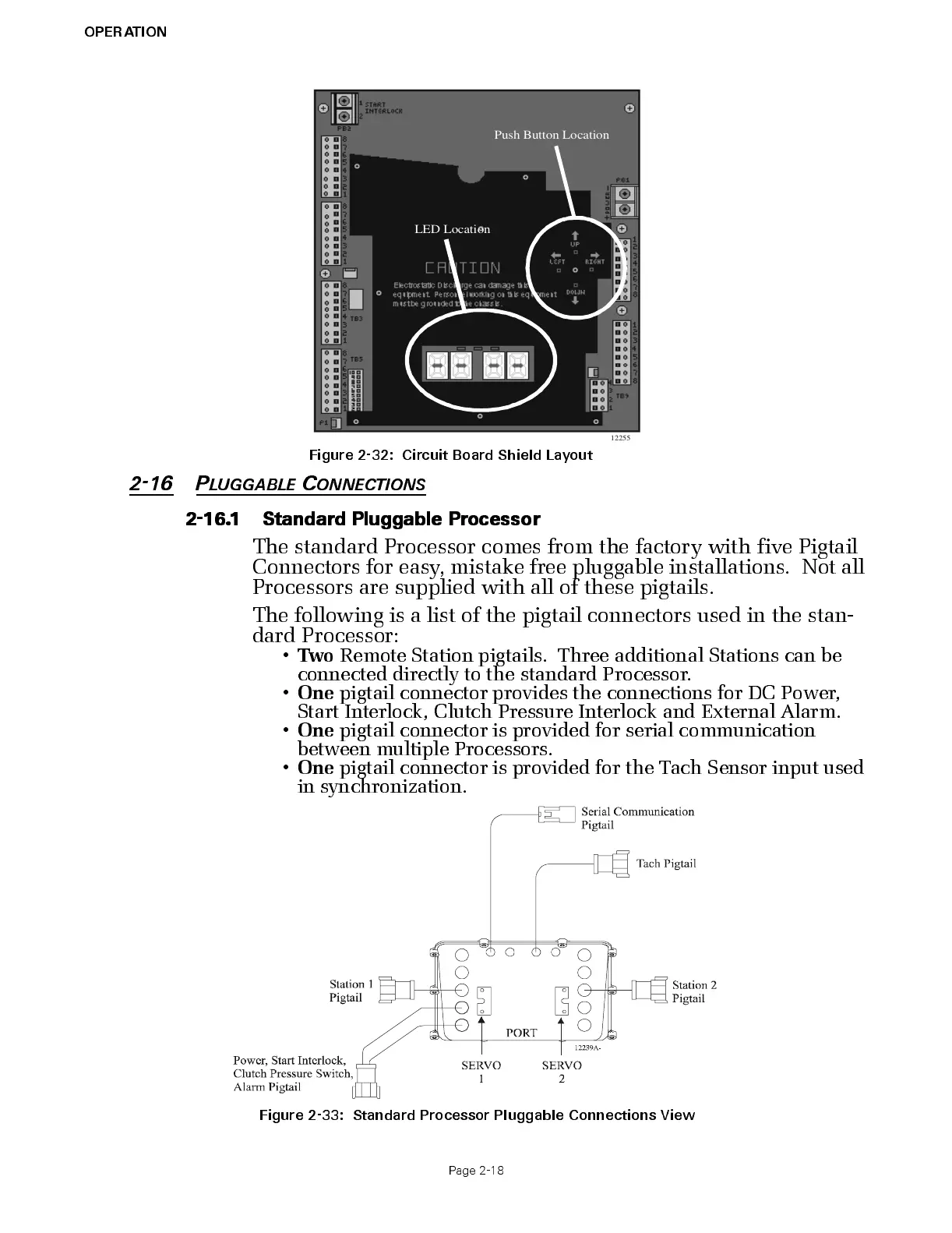
The s tandar d Proces s or c omes from the factory with five Pigta il
Conn ec tors for easy, mistake free pluggable installations. Not all
Processors ar e supplied with all of thes e pigtails.
The following is a list of the pigtail connectors used in the stan-
dard Processor:
•
Two
Remote Stat io n pi gt ails. Three additional Stations can be
connected directly to the standard Processor.
•
One
pigtail connector provides the connections for DC Power ,
Start Interlock, Clutch Pressure Interlock and External Alarm.
•
One
pigtail connector is provided for serial communication
between multiple Processors.
•
One
pigtail connector is provided for the Tach Sensor input used
in synchronization.
Fig u r e 2-3 2: Circui t Boa rd Shi e ld Layout
Figure 2-33: Standar d Pr ocessor Pluggable Connections View

 Loading...