INTRODUCTION
Page 1-3
1-2.2 9121 Pr ocessor
(Throttle-Serv o 2, Shift-Solenoid, Troll-Serv o 1)
The
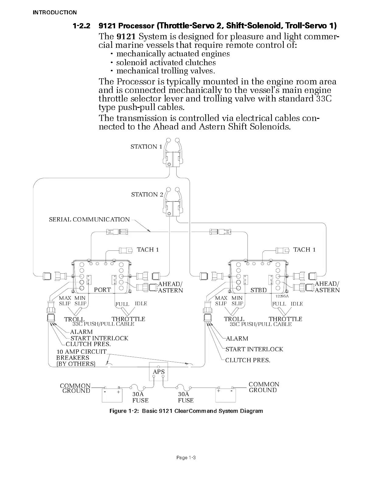
9121
Sy stem is designed f or pleasure and l ight commer-
cial marine vess els that require remote control of:
• mechanically actuated engines
• soleno id activated clutches
• mechanical trolling valves.
The Processor is typically mounted in the engine room area
and is connected mechanically to the vessel’s main engine
thro ttle s elec tor lever and trolling valve with standard 33C
type pus h-pull cables.
The transmission is controlled via electrical cables con-
nected to the Ahead and As tern Shift Solenoids.
Figure 1-2: Basic 9121 ClearCommand System Diagram
IDLE
FULL
33C PU SH / P U LL C A B LE
33C PU SH / P U LL C A B LE
IDLEFULL
THROTTLE
TROLL
THROTTLE
TROLL
STBD
STATION 2
STATION 1
PORT
12295A
SERI A L CO MM UNI CATIO N
10 AMP CIRCUIT
BREAKERS
(BY OT HE RS)
APS
CLUTCH PRES.
STA RT IN TE RL OC K
LARM
STA RT IN TE RL OC K
CLUTCH PRES.
ALARM
TACH 1 TACH 1
MAX
SLIP
MIN
SLIP
MAX
SLIP
MIN
SLIP
HEAD/
STERN
AHEAD/
ASTERN
30A
FUSE
-
+
-
+
GROUND
COMMON
GROUND
COMMON
30A
FUSE

 Loading...