OPERATION
Page 2-5
The sy stem is placed into Warm-Up Mode as follo ws :
F) When the Control Head’s lever is returned to the Neutral
detent, the red LED will discontinue blinking and remain lit
steady. After one second in Neutral, the Processor will
automatically reset to normal operation with full control of
the clutches and engine.
G) The next movement of the Control Head’s lever will engage
the Ahead or Astern clutch (Normal Operation).
2-9
H
IGH
/L
OW
I
DLE
The Control System provides the input to the engine, so that it
may run at the standard Idle speed (typically adjusted at the gover-
nor or carburetor), or it can provide a second elevated Idle speed.
2-9.1 Low Idle
• The factory default setting is for Low Idle Only.
• When the System is initially powered-up, it will always com-
mand Low Idle, even when High Idle is selected.
2-9.2 High Idle
• If High Idle is d esired, it ma y be programme d during Dock Tri-
als.
• High Idle is programmable up t o a maximum set t ing of 20% of
Full Throttle.
• High Idle is automatically selected when in Warm-Up Mode.
2-9.3 Selecting Be tween High and Low Idle
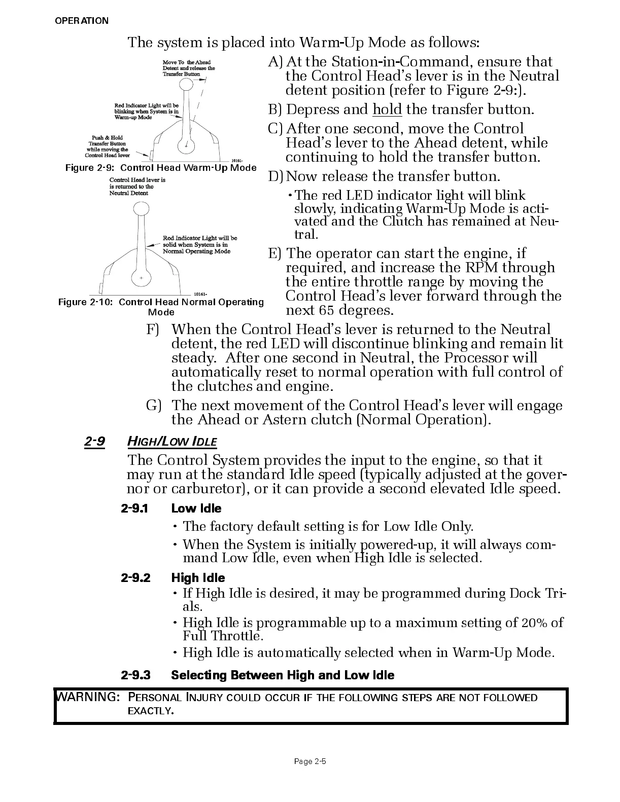
Figure 2-9: Control Head Warm-Up Mode
Figure 2-10: Control Head Normal Operating
Mode
A) At the S tation-in-Command, ensure that
the Control Head’s lever is in the Neutral
detent position (refer to Figure 2-9:).
B) Depress and hold
the transfer button.
C) After one second, move the Control
Head’s lever to the Ahead detent, while
continuing to hold the transfer button.
D) Now release the transfer button.
•The red LED indicator light will blink
slowly, indicating Warm-Up Mode is acti-
vated and the Clutch has remained at Neu-
tral.
E ) Th e operat o r ca n s ta rt th e eng i ne, if
required, and increase the RPM through
the entire throttle range by moving the
Control Head’s lever forward through the
next 65 degrees.
WARNING: P
ERSONAL
I
NJURY
COULD
OCCUR
IF
THE
FOLLOWING
STEPS
ARE
NOT
FOLLOWED
EXACTLY
.

 Loading...