OPERATION
Page 2-7
2-10.2 Turning OF F On e Lev er Oper ation
A)Place the
Master
lever
into the Neutral detent.
B)Place the inactive Control Head lever in to the Neutral detent.
• Whenever the inactive lever is moved to the Neutral detent,
One Lever operation is turned OFF. The green LED will turn
OFF, indicating that the control system is now in normal oper-
ating mode.
2-11 E
NGINE
S
YNCHRONIZATION
(T
WIN
S
CREW
)
Engine Synchronization must be selected during Set Up to have
automatic synchronization.
Synchronization is automatic and o nly operates when the Ahead
clutch is engaged, consequently it can be left ON full time. When
synchronization has been selected during set up, the Control Sys-
tem will always power-up with synchronization ON.
In order for synchronization to become active and work toward
synchronizing the engines' RP M's , the Synchronization Criteria
described in Section 2-11.2 must be met.
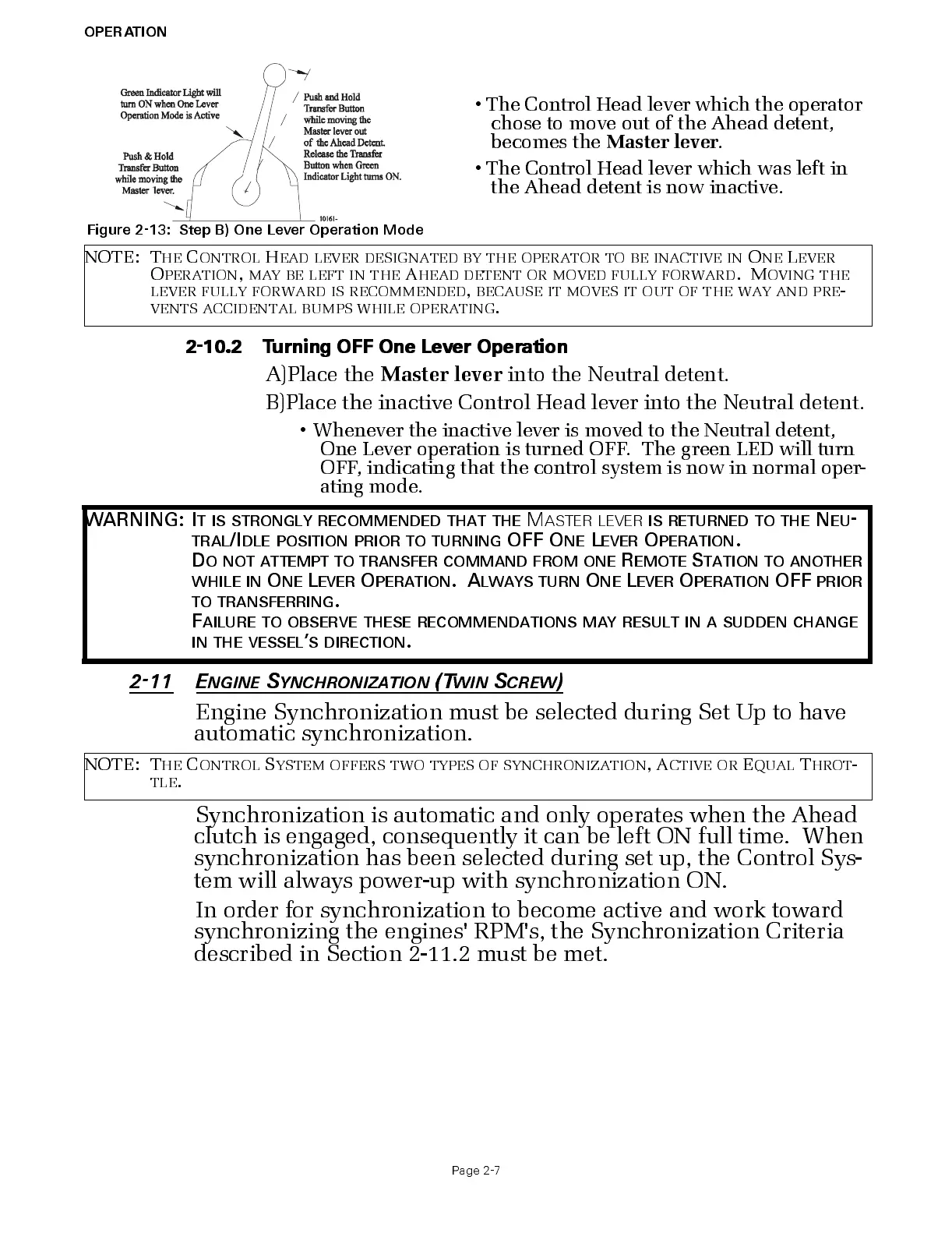
Figure 2-13: St ep B) One Lever Operation Mode
•The Contro l H ea d le ve r w hich the ope ra t or
chose to move out of the Ahead detent,
becom es th e
Master
lever
.
•The Control Head lever which was left in
the Ahead detent is now inactive.
NOTE: T
HE
C
ONTROL
H
EAD
LEVER
DESIGNATED
BY
THE
OPERATOR
TO
BE
INACTIVE
IN
O
NE
L
EVER
O
PERATION
,
MAY
BE
LEFT
IN
THE
A
HEAD
DETENT
OR
MOVED
FULLY
FORWARD
. M
OVING
THE
LEVER
FULLY
FORWARD
IS
RECOMMENDED
,
BECAUSE
IT
MOVES
IT
OUT
OF
THE
WAY
AND
PRE
-
VENTS
ACCIDENTAL
BUMPS
WHILE
OPERATING
.
WARNING: I
T
IS
STRONGLY
RECOMMENDED
THAT
THE
M
ASTER
LEVER
IS
RETURNED
TO
THE
N
EU
-
TRAL
/I
DLE
POSITION
PRIOR
TO
TURNING
OFF O
NE
L
EVER
O
PERATION
.
D
O
NOT
ATTEMPT
TO
TRANSFER
COMMAND
FROM
ONE
R
EMOTE
S
TATION
TO
ANOTHER
WHILE
IN
O
NE
L
EVER
O
PERATION
. A
LWAYS
TURN
O
NE
L
EVER
O
PERATION
OFF
PRIOR
TO
TRANSFERRING
.
F
AILURE
TO
OBSERVE
THESE
RECOMMENDATION S
MAY
RESULT
IN
A
SUDDEN
CHANGE
IN
THE
VESSEL
’
S
DIRECTION
.
NOTE: T
HE
C
ONTROL
S
YSTEM
OFFERS
TWO
TYPES
OF
SYNCHRONIZATION
, A
CTIVE
OR
E
QUAL
T
HROT
-
TLE
.

 Loading...