Page D-1
Revision List
Introduction
Refer to Bulletin 02-008 for Service Field Test Unit
(Part No. 13927) recommendations. Refer to
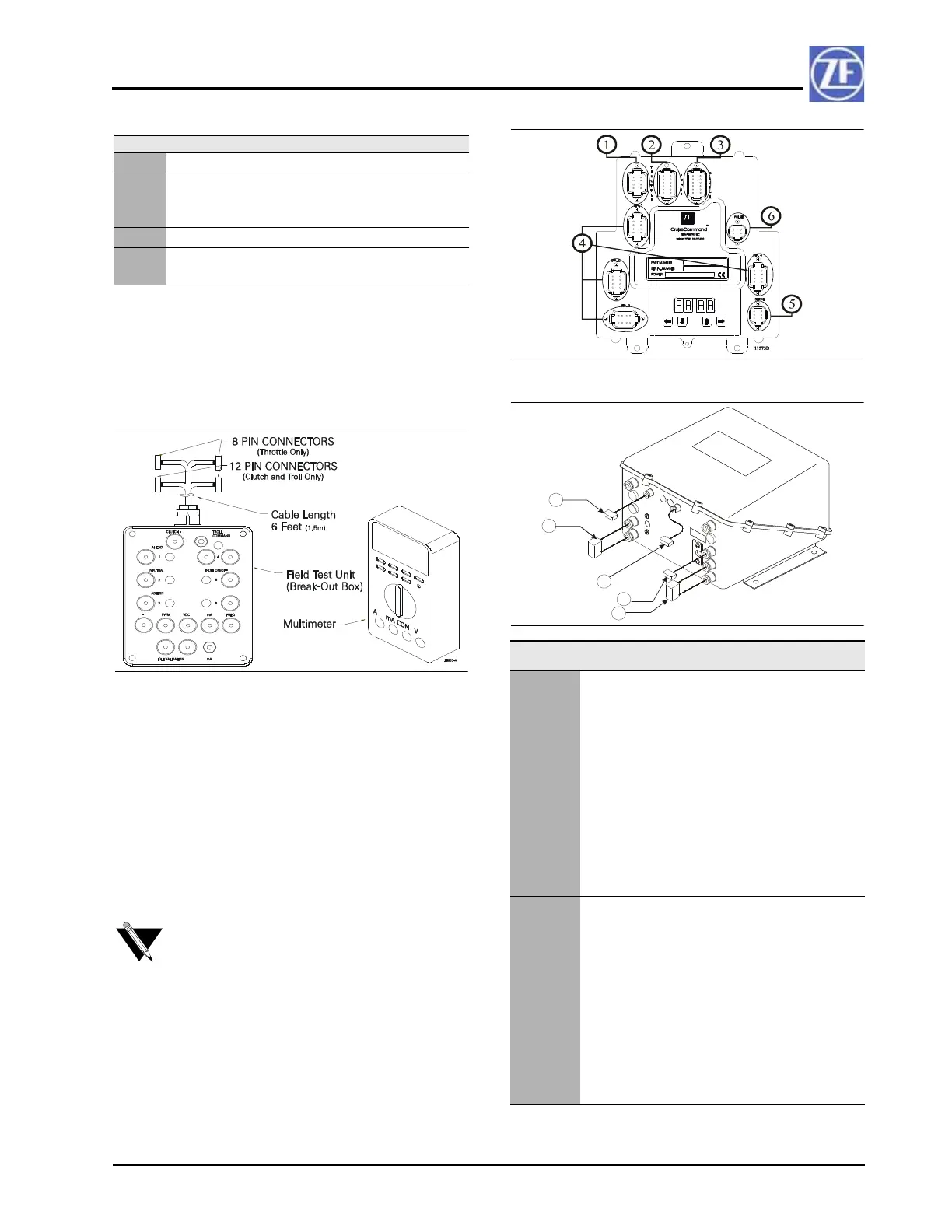
Figure D-1 for an example of the Test Unit and a
Multimeter.
FIGURE D-1: SERVICE FIELD TEST UNIT (BREAK-OUT BOX)
The Service Field Test Unit, hereafter referred to as
the “Break-out Box”, is recommended for use with
all CruiseCommand Processors (Part No. 785CE) and
with ClearCommand Processors (Part No. 9XXX
Series) that have pluggable (Pigtail) Throttle, Clutch
or Troll Connections.
The procedures for testing the various outputs of the
ClearCommand and CruiseCommand Processors are
similar, with the exception of where they connect to
the respective Processor. Figure D-2 indicates the
location of the connectors on the CruiseCommand
Processor and Figure D-3 the typical pigtail plugs on
a 9000 Series ClearCommand Processor.
FIGURE D-2: CRUISECOMMAND CONNECTOR LOCATIONS
FIGURE D-3: EXAMPLE OF CLEARCOMMAND PIGTAIL
LOCATIONS
Rev Date Revision Description
A 11/02 Revised Section 1.0 Table 1
B 2/03 Revised manual to current ZF Marine
Electronics manual standards.
Revised Section 3.0
C 4/03 Deleted Section 2.1.6
D 10/03 Revising to add 9000 Series and 2-
Speed information
NOTE: Not all ClearCommand Processors have
all of the pigtails shown in Figure D-3. Only the
pigtails that are required for a specific
application are installed in a ClearCommand
Processor.
Designation
#
Description Harness Type Harness Use
1Black 8
Pin
Throttle
Connector/
Pigtail
The throttle
signal is output
from this
connector/
pigtail. The
signal may be
in the form of
Pulse Width
Modulation
(PWM),
Voltage,
Current, or
Frequency.
2 Black 12
Pin
Power
Connector/
Pigtail
This connector/
pigtail contains
the inputs and
outputs for
Main Processor
Power, Start
Interlock,
Clutch Oil
Pressure
Interlock, and
External Alarm
Circuit.
11339-Example

 Loading...