TROUBLESHOOTING
PageB1-1
B1 TROUBLESHOOTING GENERAL
The ClearCommand Control S ystem consists of one Proces s or per
engine, typically mounted in the engine room, and one to five Control
Heads located at the vessel’s Remote Stations.
In the event that a malfunction occurs, review the appropriate Proces-
sor System Diagram and the descriptions in Section B1-1, page B1-1.
Become familiar with the various components , their functions and loca-
tion on the vessel.
Section B1-2, page B1-2, is a list of the main components that make up a
typical system, along with a brief description of their functions:
B1-1
C
ONTROL
S
YSTEMS
E
XAMPLES
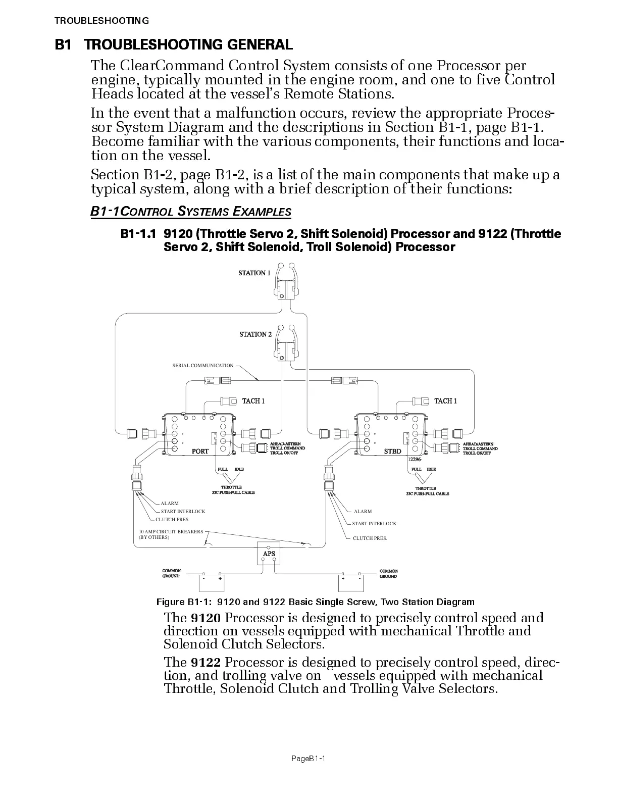
B1-1.1 9120 (Throttle Servo 2, Shift Solenoid) Processor and 9122 (Throttle
Servo 2, Shift Solenoid, Tr oll Solenoid) Pr ocessor
The
9120
Processor is designed to precisely control speed and
direction on vess els equipped with mechanical Throttle and
Solenoid Clutch Selectors.
The
9122
Processor is designed to precisely control speed, direc-
tion, and trolling valve on vessels equipped with mechanical
Throttle, Solenoid Clutch and Trolling Valve Selectors.
Figure B1-1: 9120 and 9122 Basic Single Screw, Two Station Diagram
SERIAL COMMUNICATION
(BY OTHERS)
START INTERLOCK
CLUTCH PRES.
ALARM

 Loading...