TROUBLESHOOTING
PageB1-3
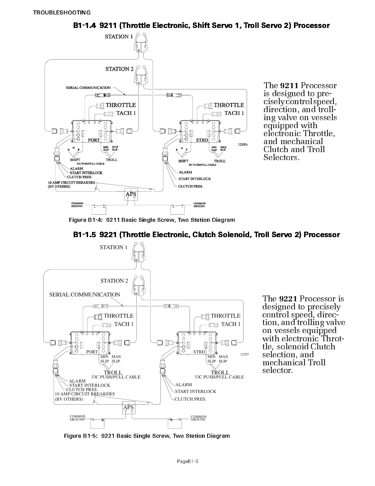
B1-1.4 9211 (Thr o ttle Elec tr on ic, Shift Servo 1, Tr oll Servo 2) Pr ocessor
B1-1.5 9221 (Thr o ttle Elec tr on ic, Clutch Solenoid, Tr oll Servo 2 ) Pr ocessor
The
9211
Processor
is design ed to pre-
cisely control speed,
direction, and troll-
ing valve on vessels
equipped with
electronic Throttle,
and mec han ical
Clutch and Tr oll
Selectors.
Figure B1-4: 9211 Basic Single Screw, Two Station Diagram
The
9221
Processor is
designed to precis ely
control speed, direc-
t ion, and trolling valve
on vessels equipped
with electronic Thr ot-
tle, solenoid Clutch
selection, and
mechanical Troll
selector.
Figure B1-5: 9221 Basic Single Screw, Two Station Diagram
3C PUSH/PULL CABLE
STBD
STATION 2
STATION 1
PORT
1229
SERIAL COMMUNICATION
0 AMP CIRCUIT BREAKERS
(BY OTHERS)
COMMON
GROUND
COMMON
GROUND
+
-+-
APS
CLUTCH PRES.
START INTERLOCK
LARM
START INTERLOCK
CLUTCH PRES.
ALARM
TROLL
MAX
SLIP
MIN
SLIP
TROLL
33C PUSH/PULL CABLE
MAX
SLIP
MIN
SLIP

 Loading...