TROUBLESHOOTING
PageB3-1
B3 TROUBLESHOOTING PROBLEM RESOLUTION
If the problem could not be resolved by asking the ques-
tions in the previous section, a careful inspection of the
Control Sy stem may be the nex t step. E ven in situations
where the problem was found and corrected, it is good
practice to always perform a careful inspection of the
entire Control System each and every time you are
asked aboard a boat.
Always verify that the installation of the System is in
compliance with the Installation Manual by carefully
inspecting t h e following:
B3-1 DC P
OWER
A) Ensure that the Processor(s) is connected to a properly
charged 12 or 24 VDC battery through a 10 Ampere cir-
cuit breaker.
B) To ensure reliable power to th e P rocessors an APS
(Automatic Power Selector) is strongly recommended.
The APS take inputs fro m two separ ate po wer sources.
W hichever power source is at the higher voltage level,
will be automatically switched through.
C) Refer to Automatic Power Selector (APS) Model:
13505, page A-25.
B3-2 C
OMPONENT
L
OCATION
B3-2.1 Control Heads
There are virtually no restrictions regarding the location of the
400 Ser ies an d MC2000 Ser ies Control Heads, as lon g as the bot-
tom is protected from the environment. The 500 Series Control
Heads must be mounted to a console and the 700 Series are
waterproof from top to bottom.
Re fer to Appendix A - Control Head Reference Sheet for Installa-
tion requirements.
B3-2.2 Pr ocessors
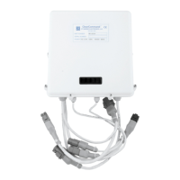
The Proc ess or s are typic ally moun ted in the engine room , while
maintaining a minimum distance of 4 feet (1,22m) from sources
of high heat and EMI (Electr o Magnetic Interfer ence) or RFI
(Radio Frequency Interference).
Refer to Section 3-1, page 3-1, for Ins tall ation r equirements.

 Loading...