MODBUS has no automatic communication parameter adaptation either, i.e. the setting of the control
technology parameters (master) must match the communication parameters of the field devices
(slave).
The master can communicate in two ways with the field devices (slaves):
•
Unicast mode – direct request to a certain field device (slave address not equal to "0"): "Regular"
operation: Master sends request to a field device to which it must reply.
•
Broadcast mode – general request to all field devices (slave address "0"): The master sends a
request (telegram) to all bus members – for example to issue an emergency command to which
none of the field devices may reply.
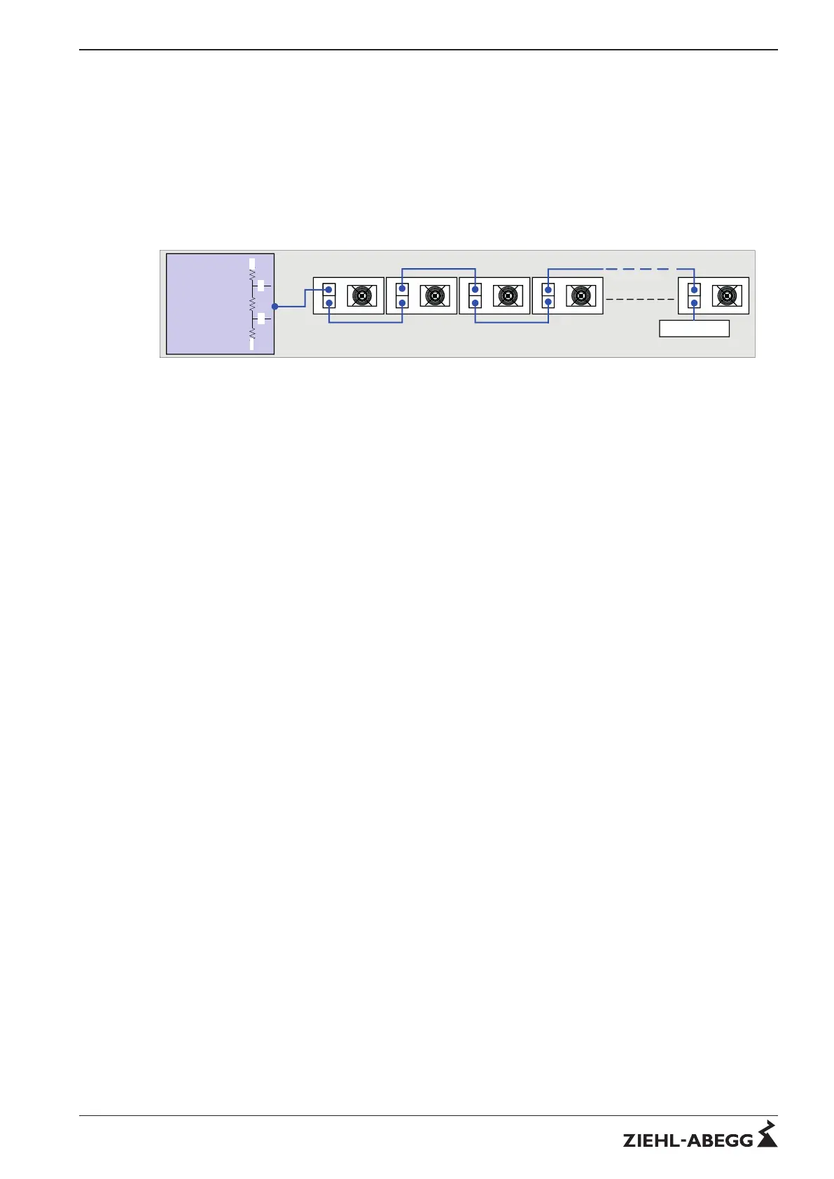
Picture 1: Structure of a channel
A node can show the following modules:
- Control device, Speed controller or Motor-Controller (Fan)
- Passive – Repeater (without intelligence)
The network channels can be connected by a passive Repeater
- Main channel (between control unit and passive repeaters with max. 63 fans)
- End channel (at the output of a passive repeater with max. 63 fans)
Attention: If the "Ziehl-Abegg-Auto-addressing" is to be used, no repeater may be used because the
repeaters cannot pass on the auto-addressing.
A special RS485 transceiver with 1/4 (1/8) UL (Unit Load) and a transfer rate of 19.2 kBd for
connecting up to 63 nodes is used to transfer the information. The cables must be laid in twisted wire
pairs (TP). The correct polarity of these lines is very important.
3 Hardware installation (Bus topology)
3.1 Two-wire MODBUS-topology
The structure of a MODBUS system is a pure bus system (daisy chain). Stub lines up to 30 cm are
permissible but should be avoided.
The implementation of the MODBUS solution by serial lines is based on an electrical "two-wire"
interface (2W - MODBUS) on the basis of the EIA/TIA-RS485 standard with master slave configura-
tion.
All the relevant information such as input and output data, parameters and diagnostic data for the field
devices can be transmitted on just two wires.
Technical information MODBUS RTU System – model series Hardware installation (Bus topology)
R-TIL08_01-GB 1215 Part.-No.
4/16
 Loading...