Information
The following line types (line impedance typically 100 Ω) are recommended for the line selection:
•
J-Y (St) 2x2x0,6
•
CAT5/7
•
AWG 22
Note
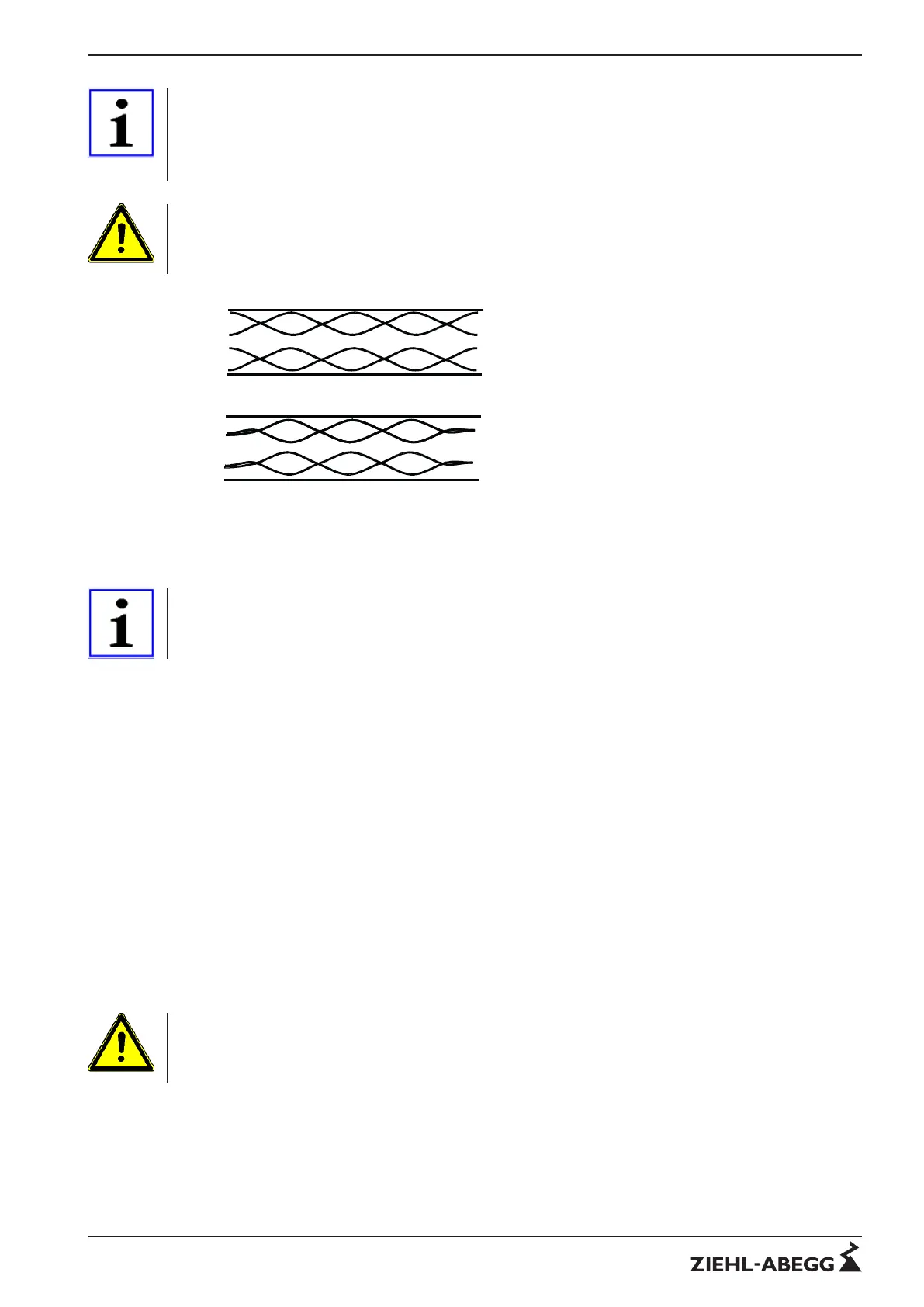
Please make sure that only two twisted wires are used for the network line for lines with more than two
wires. Parallel laying of several wires is not permitted.
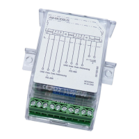
Picture 7: Line connection
The main objective in building the network must be that a smooth traffic is possible in each network
segment.
Information
Pay attention to sufficient distance from power lines and motor wires (min. 20 cm) The bus line should
be laid in a separate, conductive and earthed cable duct.
4.3 Line termination
Line terminations should be used to ensure trouble-free data transfer on the lines. The total resistance
of 54 Ω in a network is based on the specifications of EIA/TIA - 485 and should not be dropped below
of.
Terminations may only be fitted to the ends of the bus line. No more than 2 terminations may exist in
lines without repeaters.
The following devices usually contain a connectable termination (and bias resistors)
•
MODBUS-master
•
Repeater
Since the MODBUS slave devices normally have no built-in termination, an external termination (art.
no. 380080) should preferably be connected to the end of the line.
When positioning the terminating resistors following points must be observed:
•
Where are the nodes positioned?
•
Where are the repeaters positioned?
•
where the PC is placed
•
Where is the start and end of the bus?
•
What are the resulting total line lengths?
Attention
When a termination is used, must it always be positioned at the start and end of the bus?
There are different ways to avoid dropping below the specified total resistance of 54 Ω of a
network channel:
1. Insert external resistances (Ziehl-Abegg 150 Ω) on the bus
2. Use internal resistances (Ziehl-Abegg 150 Ω) at the bus connections of the repeaters
3. a combination of internal and external resistors
Technical information MODBUS RTU System – model series Physical MODBUS transmission layer
R-TIL08_01-GB 1215 Part.-No.
7/16
 Loading...