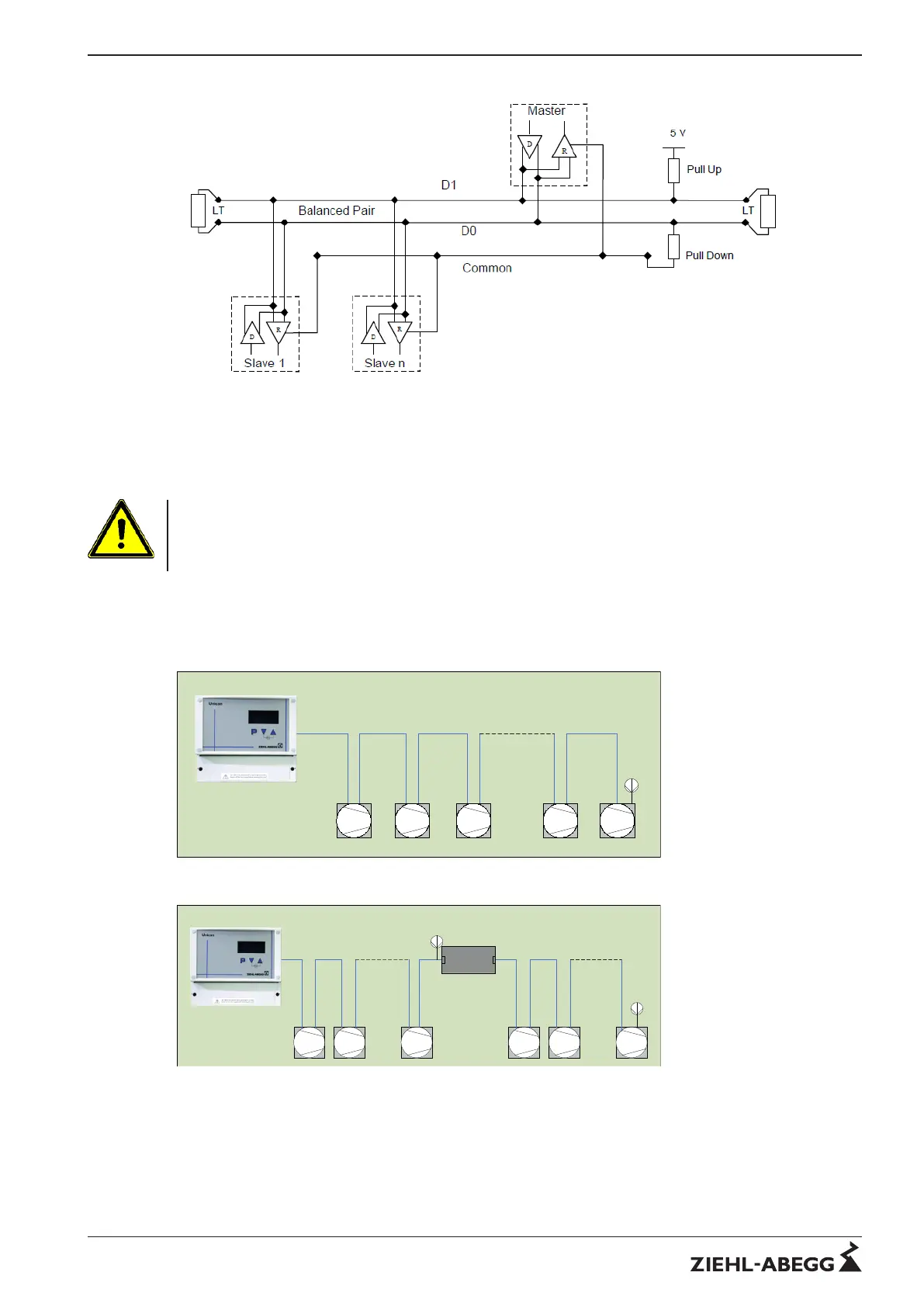
Picture 3: General two-wire topology
In addition to the two signal wires, the MODBUS line can have two other wires for the 24V supply. This
voltage is always required to supply the terminals of the "AXG" type series. The voltage can be fed in
by the first slave for example.
Attention
Wrong polarity of the supply voltage or switching of the bus wires with the supply voltage wires can
destroy the interfaces. If an RS232/RS485 converter (gateway) is used, this must be electrically
isolated.
3.2 MODBUS structuring
The following pictures show examples of an unsegmented (picture 4) and a segmented (picture 5) bus
structure.
Picture 5: Two segments connected to a repeater
Technical information MODBUS RTU System – model series Hardware installation (Bus topology)
R-TIL08_01-GB 1215 Part.-No.
5/16
 Loading...