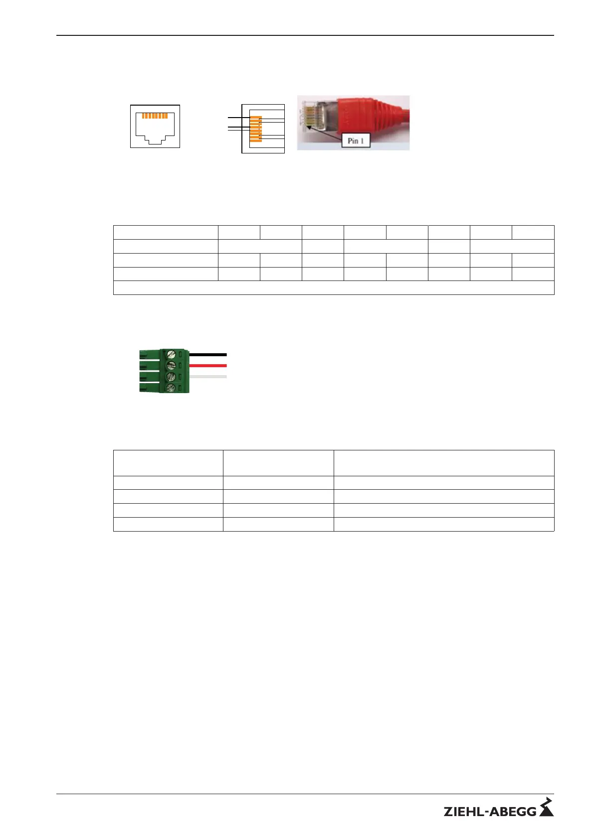
Picture 9: RJ45 MODBUS assignment
Pair assignment patch cable CAT5/7 RJ45
Pin 1 2 3 4 5 6 7 8
Pair number 3 2 1 2 4
Colour EIA/TIA 568 A WH / GN GN WH / OG BU WH / BU OG WH / BN BR
Colour EIA/TIA 568 B WH / OG OG WH / GN BU WH / BU GN WH / BN BR
Note: Pair 2 on Pin 3 + 6 !
4.5.2 Connections 4-pin Phoenix MSTB 2.5
Picture 10: Pin assignment
Assignment table
Ziehl-Abegg
Description
MODBUS
Description
Description
D- (D1) D1 (B) V1 voltage, V1 > V0 → 1 [OFF] State
D+ (D0) D0 (A) V0 voltage, V0 > V1 → 0 [ON] State
GND Common optional (circuit ground)
+24 VP optional (24V power supply)
When using telephone flex (J-Y (St) 2x2x0,6), we recommend the following allocation:
"A" (D+) = red
"B" (D-) = black
"GND" = white
"+24V" = yellow
Technical information MODBUS RTU System – model series Physical MODBUS transmission layer
R-TIL08_01-GB 1215 Part.-No.
9/16
 Loading...