7 Enclosure
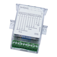
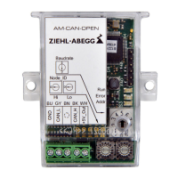
7.1 Examples for Bus signals (oscilloscope measurements)
Request node without RT without FS Request node with RT and FS
RT = Terminations resistance (150 Ω)
FS = Fail safe termination
7.2 Problem solutions
No response, no communication
A termination at both ends is recommended in RS485 networks. Communication problems may occur
if it is missing entirely or partly.
•
The transfer rate of the network interface is set incorrectly.
– Check the termination visually or with an LCR meter
– Check the continuity of the bus line with a line tester and LCR meter
– Test sections to localise the error range
– The transfer rate must be set identically for master and slave
– Slave address may only exist once per channel
•
Too many transmission errors (Transmission Errors, CRC Errors):
– The shield should always be contacted on shielded bus lines. The shield is usually contacted
on "PE"
– In systems with branches over several floors, potential shifts of the PE connections may
occur which cause a compensation current by the shield which can lead to communication
disturbances. To prevent this, the shield can be disconnected if necessary by an unshielded
adapter on one side of the bus line.
•
Interferences from the power electronics: Every power electronics has an integrated EMC line
input filter which requires a low-ohmic, low-inductance "PE" connection to work properly.
– Check "PE" connections in the branch sockets for safe contact.
– If power lines are too long, the fan housings may have to be earthed additionally
Technical information MODBUS RTU System – model series Enclosure
R-TIL08_01-GB 1215 Part.-No.
15/16
 Loading...