5.2.2 Electrical connection
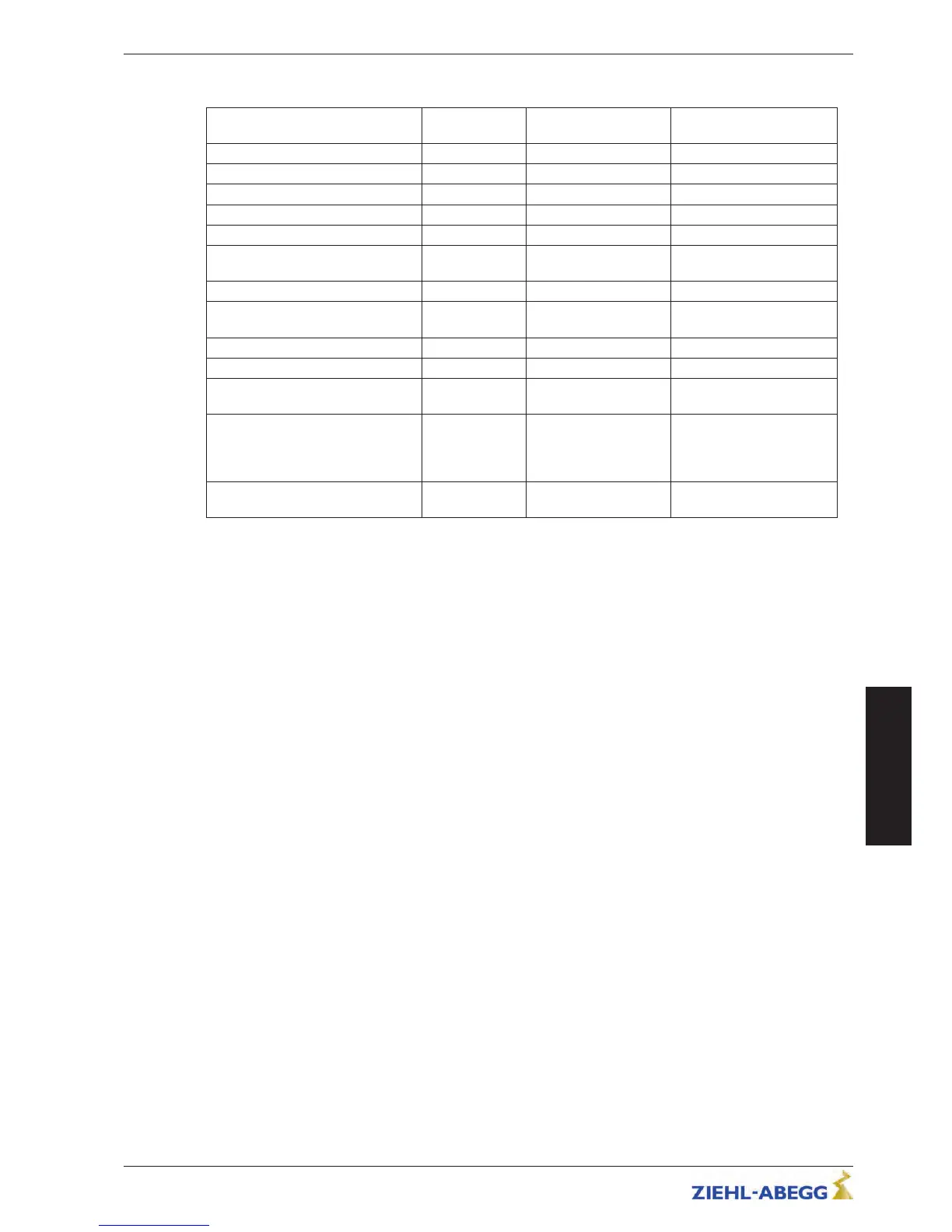
Lead Cable length Shielding ZAdynpro shield coating
version
Power line - - -
Motor cable Max. 25 m Earthed at both ends Clip on mounting plate
Brake chopper/brake resistor line Maximum 5 m Earthed at both ends Pigtail
Connecting line for standby input Max. 25 m - -
Connecting line for the digital inputs Max. 25 m - -
Connecting lines for the digital out-
puts
Max. 25 m - -
Rotary encoder line Max. 25 m Earthed at both ends Via connector
Temperature monitoring of brake re-
sistor
Maximum 5 m Earthed at the inverter
end
Pigtail
STO line Max. 50 m Earthed at both ends Pigtail
Connecting line for ZApadpro Max. 50 m Earthed at both ends Via connector
Connecting line of rotary encoder
simulation
Max. 25 m Earthed at the customer
system end
-
Connecting line for CAN interface
•
Main line:
Max. 200 m
•
Stub lines:
Max. 6 m
- -
Connecting line for brake release
monitoring
Max. 25 m - -
•
Do not twist shielding for connections; use a suitable shield connection system
•
Run the control cables and the encoder cables separate from the power cables
•
Provide connected inductances (brakes, contactors) with suppressors
•
In order to use the ZAdynpro safely and in compliance with standards, a power choke of type ND...
from ZIEHL-ABEGG must be integrated into the power line. For assignment of the frame sizes of
the ZAdynpro to the respective power chokes, refer to chapter "Electrical installation/Mains con-
nection".
•
Operating the ZAdynpro without the ND.. type power choke voids all warranty entitlements.
•
In the case of a supply line of > 25 m (motor line) or > 5 m (brake resistor line), adherence to
standard EN 12015 (Electromagnetic compatibility – Emission) and EN 12016 (Electromagnetic
compatibility – Interference immunity) can no longer be guaranteed.
•
If you must interrupt the shielding on a particular line (e.g. to install motor contactors), the shielding
must be subsequently continued with the lowest possible HF impedance.
•
Use shielded lines in the switching cabinet also
•
Feed the voltage supply of the motor contactors through the mains filter of the elevator control
Original operating instructions
ZAdynpro – Part 1 Electrical installation
R-TBA17_01-GB 1837 Index 004 Part.-No. 00163459-GB
1
3/64
5
 Loading...