Terminal assignment of X-OUT1, X-OUT2
•
The output assignments can be configured. The configuration can be implemented by:
– Presetting the used control system (assignment corresponding to the control requirements)
– Free configuration
•
Implement configuration of the digital outputs in the Control system\CONFIG menu.
•
Please refer to the "Parameter list/Control menu" chapter for a description of the individual
parameters
The output assignments dependent on the configuration:
Configuration
1)
Outputs
O11 - O14 O21 - O24 O31 - O34 O41 - O44 O51 - 54
00:Free Err* MB_Brake* MotContact* V < V_G1* STO-Info*
01:ZA_IO Fault MB_Brake MotContact V < V_G1 STO-Info
03:BP_IO Fault MB_Brake MotContact V < V_G1 STO-Info
08:KN_IO Fault MB_Brake MotContact V < V_G1 STO-Info
11:NL_IO Fault MB_Brake MotContact V < V_G1 STO-Info
13:SS_IO Fault MB_Brake MotContact V < V_G1 STO-Info
15:ZA_BIN Fault MB_Brake MotContact V < V_G1 STO-Info
16:WL_IO Fault MB_Brake MotContact V < V_G1 STO-Info
21:ST_IO Fault MB_Brake MotContact V < V_G1 STO-Info
24:CSILVA Fault MB_Brake MotContact V < V_G1 STO-Info
25:S+S MotContact MB_Brake V=O Fault STO-Info
27:MAS_BIN Fault MB_Brake MotContact Off* STO-Info
30:KS_IO Fault MB_Brake MotContact V < V_G1 STO-Info
31:KL_IO fault MB_Brake MotContact EVAC.DIR STO-Info
32: S_SMART Fault MB_Brake MotContact SD STO-Info
1) For the description of the configurations, see chapter "Parameter List/Control Menu" in the operating instructions - Part 2.
* The function of the inputs can be changed
5.11 CAN interface (X-CAN)
Designation of the con-
nection terminal:
X-CAN
Line cross-section:
Type of cable:
•
N
ot shielded
•
Twisted pair
Cable lengths:
•
Main line: Max. 200 m
•
Stub lines: Max. 6 m
Connection type: Screw terminals
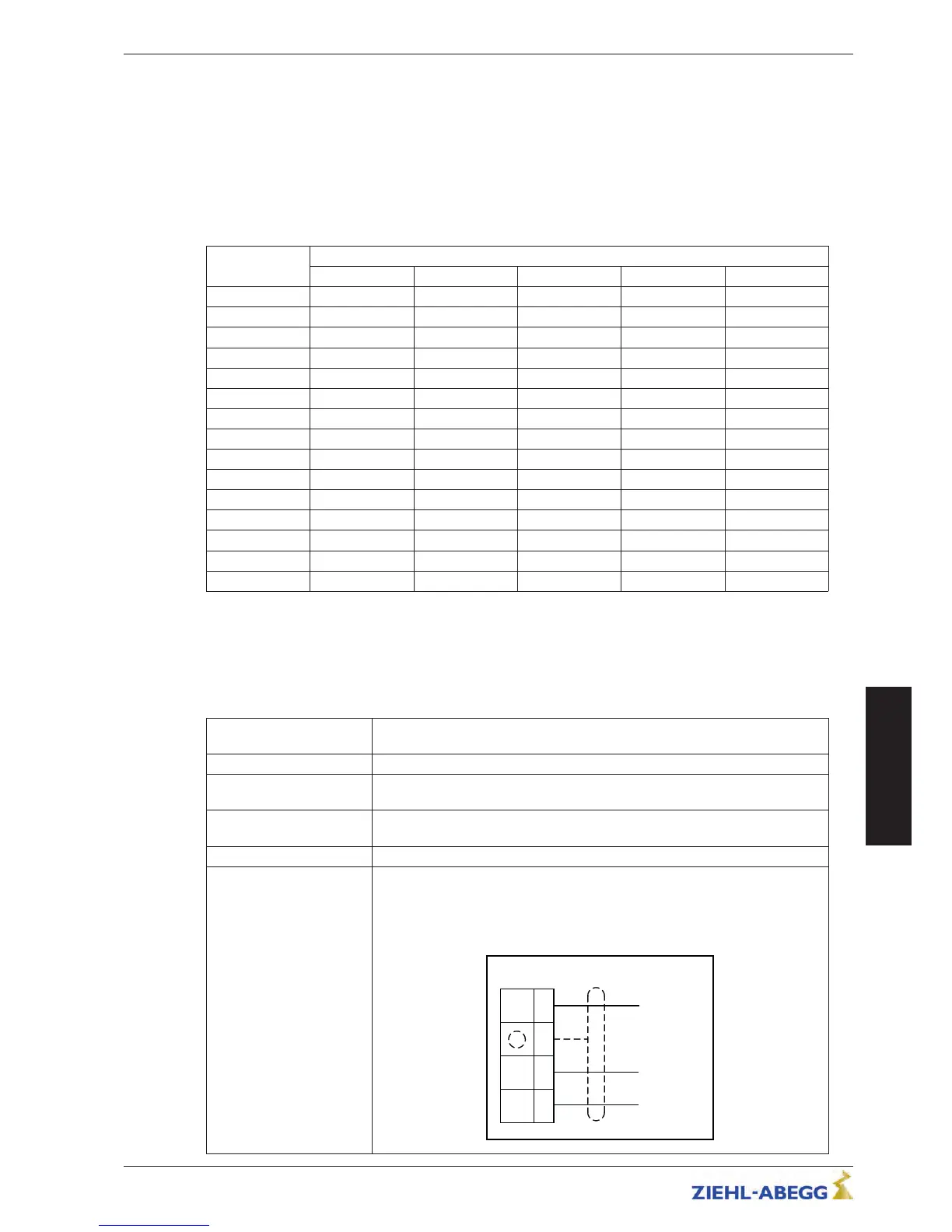
Connection:
•
The wiring is in a linear structure. The individual devices are connected to
the main line with short stub lines.
•
The bus should be terminated with a terminating resistor of
120 - 150 Ohms, at both ends of the bus.
 Loading...