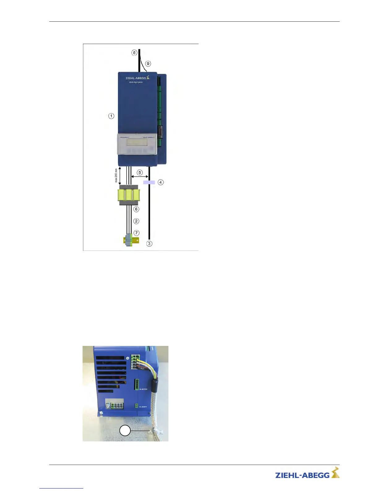
5.2.3 EMC-compatible assembly of the control cabinet
1 ZAdynpro mains connection terminal
2 Power line
3 Motor cable (shielded)
4 Clip for fixing the shielding
5 Route electrical lines with the maximum possible spacing
6 Line reactor
7 Mains connection
8 Brake resistor cable (shielded)
9 Shielding (brake resistor cable)
The following points must be observed if the stand-
ards outlined in chapter "EMC-compatible installa-
tion/Standards" are to be adhered to:
•
Refer to chapter "EMC-compatible installation/Stan-
dards"
•
Cable length between power choke and ZAdynpro
maximum 200 mm
•
Route the power line (including the mains connection
terminal and power choke) separately from the brake
resistor line and the motor line
5.2.4 Motor cable
•
The shielding of the motor line must be extensively connected to the earth potential in the
immediate vicinity of the ZAdynpro. The shielding must be continued right up to the connection
terminal.
•
We recommend fixing the shielding on the mounting plate by means of a clip (see Fig.).
Fixing the shielding on the mounting plate
1
Clip
Original operating instructions
ZAdynpro – Part 1 Electrical installation
R-TBA17_01-GB 1837 Index 004 Part.-No. 00163459-GB
1
4/64

 Loading...