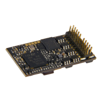
Page 68 MS - SOUND decoders MS440 to MS990 and MN - NON-SOUND decoders MN170 to MN340
Allocation of
Function outputs
as (for example)
low/high beam
ATTENTION:
Certain settings in
CV #154 (Special
output configurations
for OEM projects)
the meaning of the
following CVs
changes:
#119, #120,
i.e. those are not low
beam mask any-
more.
Typical application: Low/high beam
Bit 0 - front headlights
Bit 1 - rear headlights
Bit 2 - function output FO1,
Bit 3 - function output FO2,
Bit 4 - function output FO3,
Bit 5 - function output FO4,
Bit 6 - function output FO5.
Respective Bit = 0: Output will not be dimmed,
Respective Bit = 1: Output will be dimmed with F6
to value defined in CV #60.
Bit 7 = 0: “normal“ effect of F6.
= 1: Inverted effect of F6.
EXAMPLE:
CV #119 = 131: Headlights shall be switched between
high and low beam with F6 (F6 = 1).
Same as CV #119 but with F7 as low beam key.
Adaptive
Acceleration and de-
celeration momen-
tum
Raising or lowering the speed to the next internal step oc-
curs only if the preceding step is almost reached. The tol-
erance for reaching the preceding step can be defined by
this CV (the smaller this value the smoother the accelera-
tion/deceleration).
Value 0 = no adaptive accel. or decel.
Tens digit: 0 - 9 for acceleration (1 = strong effect)
Ones digit: 0 - 9 for deceleration
= 11: strongest effect;
ATTENTION:
Bits 2, 3, 4, 6 (i.e.
selection for shunt-
ing key functions)
are only valid if CVs
#155 and #156 = 0
(These allow ex-
tended selection and
are preferred for
new projects).
Shunt key functions:
Half-speed, acceler-
ation deactivation
Bits 0,1 (i.e. type of
acceleration deacti-
vation) are always
valid, also together
with CVs #155, #156
Bit 7:
Switchover SUSI -
Logic level outputs
Selection of a shunting key to activate the HALF SPEED:
Bit 4 = 1 (and bit 3 = 0): F3 as half-speed key
Bit 3 = 1 (and bit 4 = 0): F7 as half-speed key
Selection of a marshalling key for deactivation of ACCEL-
ERATION TIMES:
Bit 2 = 0 (and bit 6 = 0): MN key as acceler. deact.
Bit 2 = 1 (and bit 6 = 0): F4 as acceleration deactivation
Bit 6 = 1 (bit 2 irrelevant): F3 as acceleration deact.
Type (range of action) of key (MN, F3 or F4) for deac-
tivating acceleration times:
Bits 1,0 = 00: no influence on acceleration times
= 10: reduces acceleration/deceleration time
to ¼ of the values according to CVs #3, #4.
= 11: deactivates acceleration/deceleration time
completely.
EXAMPLES:
F3 as half speed key, if CV #124 = 16
F3 as half speed key and
F4 to completely disable acceleration/deceleration time,
if bits 0, 1, 2, 4 = 1, so CV #124 = 23
F3 as half-speed key and for Accel. deact.
if bits 0, 1, 4, 6 = 1, i.e. CV #124 = 83
Bit 7 = 0: SUSI interface active (or servos,
if defined in CVs #181, #182, ...
= 1: Logic level activated instead of SUSI.
Effects
American
lighting effects, and
Bits 1, 0 = 00: bidirectional (active in both directions)
= 01: only active in forward direction
= 10: only active in reverse direction
other effects,
couplings, smoke
generators, etc.
on the FO
“Front light”,
Configurations and
modifications
of the effects by
CVs #62, #63, #64,
and CV #115, #116
(for coupler).
ATTENTION in case of CV #125 and #126: change CVs
#33, #34.... if direction is wrong!
Bits 7, 6, 5, 4, 3, 2 = Effect-Code
EXAMPLES (Effect - value programmed into CV #125)
Mars light, only forward - 00000101 = “5”
Gyralite, independent of direction - 00011100 = “28”
Ditch type 1 left, only forward - 00100101 = “37”
Uncoupler -00110000 = “48”
Soft start of output - 00110100 = “52”
Automatic Brake light -00111000 = 56
Automatic Cab light OFF - 00111100 = “60”
Speed/load depen. Smoke - 01001000 = “72”
Speed/load depen. Diesel smoke - 01010000 = “80”
Effects
on function output
rear light
See CV #125 for details
#125 → Front headlight
#126 → Rear headlight
Effects on
FO1, FO2, FO3,
FO4, FO5, FO6
See CV #125 for details
#127 → FO1 #128 → FO2
#129 → FO3 #130 → FO4
#131 → FO5 #132 → FO6
Using FO4 as
Cam-sensor output
for the module of
your choice
or
FO4 as output for
Steam fan of the
Smoke generator of
steam locos
Reed configuration
= 0 (Default): FO4 is used as normal function output
so it’s controllable by function key instead of a cam
sensor.
= 1: FO4 for smoke-fan whcih is usually controlled by a
real or “virtual” cam sensor. Also see CVs #267,
#268!
NOTE: The fan operation is also determined by the
sound project.
NOTE: Large-scale decoders do have special outputs
and additional configuration possibilities for smoke fans!
Bit 4 – inverts the polarity of Reed input 1
Bit 3 – inverts the polarity of Reed input 2
Bit 2 – inverts the polarity of Reed input 3
Bit 5 – inverts the polarity of Reed input 4
Bit 6 - (only types MS440) Pin IN4 becomes output FA9
1 - 14,
101 - 114,
201 - 214
Smoothing (hundreds digit), threshold (tens digit, ones
digit).
Fine adjustment of
the speed feedback
or km/h - control no.
calibration run
RailCom speed feedback correction factor.
or (see chapter 5.8 in manual for small decoders)
reading out the result of the internally computed speed af-
ter the calibration run.
Definitions of
smoke generator
characteristic, con-
nected to FO1 – 6.
PWM at stand still
PWM at steady
speed
PWM during accel.
This is valid, if in one of the CVs #127 - #132 has set on
of the function effects “smoke generation” (i.e. “72” or
“80”): The values in CVs #137 – #139 define a character-
istic for the function outputs (FO1 - FO8; referred to be-
low as FOx).
CV #137: PWM of FOx at standstill
CV #138: PWM of FOx at steady speed
CV #139: PWM of FOx at acceleration
 Loading...