Installation instructions
805845UK V1.02 July 2018 - G4 Command Centre
Technical support
Tel: 0345 6 005 005 Email: service@zipindustries.co.uk www.zipwater.co.uk
1.2.2 Preferred ventilation arrangement shown below.
The ducted vent kit supplied with the Command Centre exhausting through the kick-space should be used, to
provide adequate ventilation in all conditions. (Ancillary components are not shown in these diagrams).
A
B
C
Position vent grille on
either the kick board or the
cupboard ends
Inlet grille should be
fitted in baseboard
A
Cupboard back must be
fully closed to prevent
recirculation into
cupboard from
kick space.
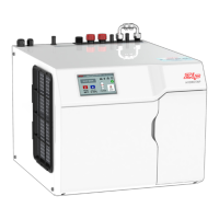
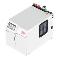
1.2 BC, BCS Commercial Command Centres
Ventilation
1.2.1 Ventilation for all models
• The clearance envelope dimensions stated in the Specification sheets and Installation instructions must
be observed.
• Adequate ventilation must be provided to ensure that the cupboard temperature doesn't exceed 35
0
C.
Vent cut-out details
A Air outlet vent
(flat vent)
B Air inlet vent
314
Ø
12 x 2
326
5
43max
285
60
Ø
12 X 4
=
=
45
284
Ø
12 x 4
C Ducted vent