Installation instructions
805845UK V1.02 July 2018 - G4 Command Centre
Technical support
Tel: 0345 6 005 005 Email: service@zipindustries.co.uk www.zipwater.co.uk
1.6.3 Alternative arrangement
• For high use applications where the cupboard space
temperature is near 35
0
C or higher, the vent kit supplied can
be used to provide further ventilation by convection.
Note The vent kit has to be installed in a way that allows air
to be drawn in from the bottom of the cupboard and expelled
through the top of the cupboard. The outlet vent should be
towards the top of the door (position A1) or side of the cupboard
(position A2).
(Where possible air inlet vent and the air outlet vent should be
positioned at opposite ends of the same cupboard space).
1.6.1 Ventilation for all models
• The clearance envelope dimensions stated in the specification sheets and installation instructions must
be observed.
• Adequate ventilation must be provided to ensure that the cupboard space temperature does not exceed
35
0
C.
1.6.2 Preferred arrangements
4mm door buffers (at the four corners of each door) supplied with the Command Centre
should be used to
provide adequate ventilation in normal usage, see illustration below.
Door buffer
Vent cut-out details
A1 or A2 Air outlet vent
B Air inlet vent
Note Flat outlet vent
detail shown, louvred
outlet vent also supplied.
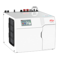
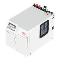
1.6 BC, BCS, CS, C Residential Command Centres
Ventilation
314
Ø
12 x 2
326
5
43max
285
60
Ø
12 X 4
=
=