Fault Finding
Note: All servicing and repairs must be undertaken by a competent person,
familiar with unvented systems.
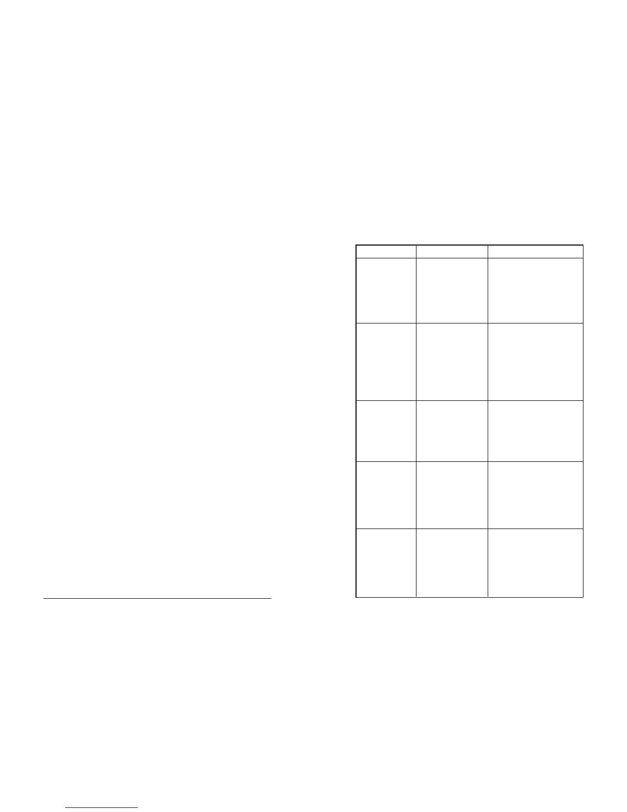
Fault Possible Cause Solution
Over temperature The thermostat has failed Reset. If the cut-out operates
cut-out operates again isolate the unit and contact
The thermostat is set at the installer. Note: Isolate the
too high a temperature electrical supply before
removing the electrical cover
panel and ensure that the
panel is correctly replaced and
secured before reconnecting
Regular, intermittent Loss of pressure from the Isolate the heating system and
water discharge from expansion vessel the mains cold water supply.
tundish Partly drain the unit. Recharge the
expansion vessel to the specified
pressure and re-commission.
Thermostat failure Isolate the heating system and
check thermal controls when
discharge ceases. Replace
thermostat if faulty.
Continuous water Pressure reducing valve Check with pressure gauge and
discharge from not operating correctly replace as necessary
the tundish
P&T relief valve not Check and replace if faulty
operating correctly
Expansion relief valve Check and replace if faulty
not operating correctly
No water flow from Cold water mains supply Restore mains supply to the heater
hot taps isolated
Integral line strainer in Check and clean as necessary
pressure reducing valve
has become blocked
Pressure reducing valve Refit correctly with arrows in
incorrectly fitted direction of flow
Water from hot taps Power supply not Check and switch on
is cold switched on
Over temperature See fault "Over temperature
cut-out has operated cut-out operates" above
Faulty element Check and replace as necessary
Thermostat failure Check and replace as necessary
AP3/30, AP3/50, AP3/80, AP3/100 Installation Instructions 12
are specifically excluded under the terms of the warranty. To reduce
lime-scale formation to a minimum the unit should always be operated at
the lowest convenient temperature. The ‘E’ temperature setting is
recommended
10. If the unit has been commissioned and is to be unused for more than
two weeks with the power supply still connected the thermostat should
be set to ‘*’ to maintain a temperature of approx. 9ºC and protect the unit
from freezing. Note: this protection does not extend to connecting
pipework. It is recommended that the cold supply is turned off
and several litres of water drawn off through a hot tap. Note: The cold
supply must be re-opened prior to use. If power has been
disconnected it is recommended that the unit is drained (see draining)
11. The Zip Aquapoint is fitted with a sacrificial anode to provide additional
protection against corrosion. Gradual erosion of the sacrificial anode
will occur depending upon local conditions which in extreme cases
may cause rapid erosion of the anode resulting in particles being
deposited as a residue. The Aquapoint should not, therefore, be used
in applications where water quality is critical. Regular preventive
maintenance inspections are vital to achieve optimum performance and
durability of the appliance. The condition of the anode should be
checked regularly by an authorised Zip service provider as part of the
preventive maintenance programme.
Schedule
It is recommended that all key components of the heater should be inspected
on a regular basis, no greater than twelve monthly intervals, for continued safe
and efficient operation. The inspection should be carried out by a competent
person familiar with unvented systems and the components to be inspected
should include the following:
1. Expansion relief valve. Check for correct operation
2. T&P relief valve. Check for correct operation
3. Check expansion vessel pressure – refer to label on vessel for correct
pressure
4. Inspect integral line strainer and clean as necessary
5. Check that the discharge pipework is free of any obstructions
6. Check that all electrical connections are tight
7. Check condition of the sacrificial anode by disconnecting the wire
between the anode and vessel and verifying that the current between
anode and vessel exceeds 0.1mA ensuring that the wire is re-connected
afterwards. If the current between anode and vessel does not exceed
0.1mA the anode should be checked visually and replaced if necessary
11 AP3/30, AP3/50, AP3/80, AP3/100 Installation Instructions
 Loading...