Components supplied with the unit for site fitting
• Inlet manifold assembly comprising pressure reducing valve with integral
line strainer and expansion relief valve with check valve and balanced cold
water take off.
• Expansion vessel and wall fixing bracket
• Zip Aquapoint hot water cylinder wall locating bracket
• Tundish
Installation
Requirements
General
Prior to installation the Zip Aquapoint should be kept upright in its original
packaging and handled with care always lifting from underneath.
The Zip Aquapoint should be stored in a covered, dry area protected at all times
from the weather.
These instructions must be read and fully understood before commencing
the installation. If in doubt, or in need of further guidance please ring Zip on
0870 6088888.
Installation must only be undertaken by a competent person holding a current
Registered Operative Identity card for the installation of unvented domestic hot
water storage systems issued by an accredited body.
The Zip Aquapoint must be installed in accordance with these instructions
and all current legislation, codes of practice and regulations governing the
installation of unvented hot water cylinders in force at the time of installation.
All connections should be made to the Zip Aquapoint and its safety devices
using the 15mm or 22mm compression fittings, nuts and olives supplied.
The electrical installation including earthing and cross bonding must comply
with the current IEE regulations and any Local Authority requirements.
The cold water feed manifold assembly comprises a pressure reducing valve
with integral strainer, expansion relief and check valve, factory fitted pressure
and temperature relief valve and expansion vessel. All of these components
must be included in the installation. The pressure settings on these components
are factory set and indicated on the top of the valve. Do not break any seals
or attempt to adjust any safety valve; to do so may impair the safety of the
installation and will invalidate the warranty.
It is recommended that the unit is installed according to these instructions.
Under no circumstances should the expansion relief valve be installed in an
inverted position as fouling of the seat caused by deposits may prevent it from
operating correctly.
AP3/30, AP3/50, AP3/80, AP3/100 Installation Instructions 4
3 AP3/30, AP3/50, AP3/80, AP3/100 Installation Instructions
Dimensions
Aquapoint Capacity Width Height Depth Weight Weight
(litres) (mm) (mm) (mm) Empty (kg) Full (kg)
AP3/30 30 420 525 445 19 49
AP3/50 50 420 690 445 24 74
AP3/80 80 420 950 445 28 108
AP3/100 100 420 1125 445 31 131
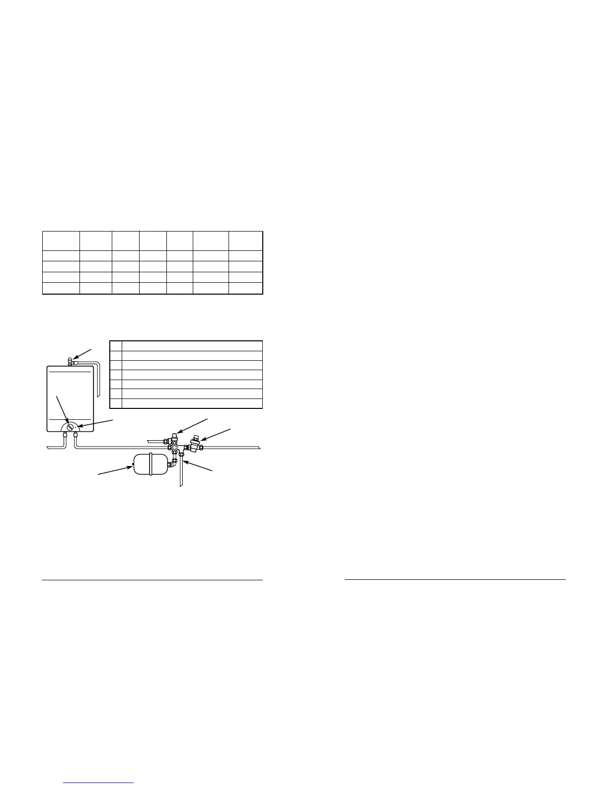
Parts List
1 Temperature and pressure relief valve
2 Combined strainer and pressure reducing valve
3 Expansion relief and check valve
4 Balanced cold water take off
5 Expansion vessel
6 Temperature control
7 Neon indicator
The Zip Aquapoint hot water cylinder will be delivered in its carton with the
various control valves and fittings supplied in a separate carton. Both should be
left packed until needed.
Factory Fitted Components
• Heating elements
• Thermostats with over temperature cut-outs
• Pressure and temperature relief valve
1
2
3
4
5
7
To drain
via tundish
Hot water
outlet
Cold water
supply
6
 Loading...