Page 6 of 16 Zip Hydro Tap Installation and Operating Instructions - 81759 - February 2013 v2.01
Installation procedure continued
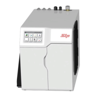
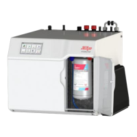
Step B - Installing the undersink unit
SPECIAL NOTE: The HydroTap undersink units are heavy, take note of the weights
listed in the table on page 4. If you think you cannot lift the unit safely, get help
and avoid possible injury.
Before positioning the heater connect the braided water inlet hose (supplied) to the
cold water inlet on the unit. This is located at the rear of the unit.
Position the Zip HydroTap undersink unit as close as possible to directly beneath
the Zip HydroTap tap head.
The connection tubes supplied with the tap head assembly CANNOT be lengthened.
Leave at least a 50 mm air-gap without obstruction on each side of the unit.
Adjust both cupboard door hinges and attach the supplied rubber door buffers to
the doors to create a 4 mm air-gap between the doors and the cupboard. This is
the minimum ventilation requirement for low usage installations.
Proper air circulation must be provided for all Chilled models. The system
will operate correctly only if the recommended air gaps are achieved during
installation. A ventilation hole measuring 100mm must be cut into the top half
of the cupboard door to accommodate the air vent provided. Make sure that the
undersink unit ventilation grilles are not obstructed in any way.
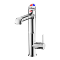
Step C - Connecting the tap
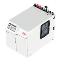
Measure and trim the blue tube and connect it to the chilled water outlet located
on the top front, right hand side of the undersink unit. Use spring clamps provided.
Measure and trim the unmarked tube and connect it to the vent outlet.
NOTE: All tubes must have a continuous fall back to the undersink unit.
Connect the tap USB connector to the USB port on the undersink unit. Orient the
USB plug carefully and connect, do not force the plug. Once connected, fix the
cable to the wall, ensure it is away from any possible water splashes and is off the
floor.
Note: When trimming any silicon tubes trim to minimum length, do not loop any
excess or allow kinking of the tubes. When connecting, slide the tube over the pipe
at least 25mm. There are black plastic clamps provided on the chilled hoses to
choke the flow if required. Only choke the flow if it is excessively strong.
Note:
Included in the installation pack are
adhesive backed silicon buffers. If air
vents are not installed in the cupboards
housing the HydroTap, the buffers must
be placed on the inside edge of the
cupboard door to create a slight gap
ensuring a minimum airflow. Failure
to do this may cause the HydroTap to
overheat and operate inefficiently.
This instruction is critical
Vent line
Chilled line
Cold outlet
Chiller Only Unit
Front
 Loading...