4
© Copyright 2017 Zoeller
®
Co. All rights reserved.
Electrical Data (continued)
Amps
Winding
Resistance
Line-to-Line
Model RPM Voltage Phase Hertz Full Load In Air Shut Off Locked
Rotor
F6292 3450 230 3 60 5.2 3.5 24.0 5.7/4.6
J6292 3450 200 3 60 6.4 4.0 23.6 6.25/5.12
G6292 3450 460 3 60 2.9 1.7 12.0 22.8/18.5
BA6292 3450 575 3 60 2.4 1.7 11.3 38.0/33.0
V6292 2800 220 1 50 7.4 3.8 12.0 4.74/3.88
AK6292 2800 380 3 50 3 1.7 10.0 22.8/18.5
E6293 3450 230 1 60 10.2 6.6 20.1 3.06/2.51*
I6293 3450 200 1 60 12.0 7.5 26.8 2.11/1.72*
J6293 3450 200 3 60 8.2 5.2 31.1 3.74/3.06
F6293 3450 230 3 60 7.6 5.2 29.8 5.7/4.5
G6293 3450 460 3 60 4.0 2.6 14.9 22.6/18.2
BA6293 3450 575 3 60 3.3 2.1 10.0 38.8/34.5
V6293 2800 220 1 50 8.2 5.2 17.0 3.05/2.51
AK6293 2800 380 3 50 3.5 2.3 12.0 22.6/18.2
E6294 3450 230 1 60 13.7 9.7 45.7 1.29/1.05*
I6294 3450 200 1 60 17.8 11.6 54.5 .86/.71*
J6294 3450 200 3 60 10.8 6.2 45.2 2.62/2.14
F6294 3450 230 3 60 9.5 5.6 39.4 3.5/2.8
G6294 3450 460 3 60 4.8 2.8 19.7 13.9/11.3
BA6294 3450 575 3 60 3.8 2.2 15.9 20.6/18.3
V6294 2800 220 1 50 14.3 11.3 45.0 1.29/1.05
AK6294 2800 380 3 50 4.7 2.3 20.0 13.9/11.3
E6295 3450 230 1 60 17.1 12.0 45.7 1.29/1.05*
I6295 3450 200 1 60 20.5 14.7 54.5 .86/.71*
J6295 3450 200 3 60 14.3 8.8 45.2 2.62/2.14
F6295 3450 230 3 60 12.2 7.5 39.4 3.5/2.8
G6295 3450 460 3 60 6.1 3.8 19.7 13.9/11.3
BA6295 3450 575 3 60 4.9 3.0 15.9 20.6/18.3
E6404 1725 230 1 60 12.9 9.9 44.8 1.80/1.60*
I6404 1725 200 1 60 14.4 11.5 49.6 1.42/1.28*
J6404 1725 200 3 60 13.8 13.1 56.8 1.6/1.3
F6404 1725 230 3 60 10.5 9.7 44.6 2.3/2.0
G6404 1725 460 3 60 5.2 4.8 22.3 9.1/8.0
BA6404 1725 575 3 60 4.1 3.8 17.6 14.6/12.7
E6405 1725 230 1 60 19.0 9.3 44.8 1.80/1.60
I6405 1725 200 1 60 20.2 8.8 49.6 1.42/1.28*
J6405 1725 200 3 60 14.8 12.5 56.8 1.6/1.3
F6405 1725 230 3 60 12.2 9.7 44.6 2.3/2.0
G6405 1725 460 3 60 6.1 4.8 22.3 9.1/8.0
BA6405 1725 575 3 60 4.8 3.8 17.6 14.6/12.7
* Line to line reading will only reect the run winding resistance.
Start winding resistance can only be measured after removing the cover.
(1) Pumps with power cord length less than 10 m (33') are intended for indoor use only.
(2) Electrical wiring and protection must be in accordance with governing electrical codes
and any other applicable electrical requirements.
(3) Install proper Zoeller
®
Unicheck (combination union and check valve), preferably
just above the basin, to allow easy removal of the pump for cleaning or repair. On
sewage, efuent or dewatering, if high head or below cover installation is required,
use 30-0152 on DN40 (1-1/2") and DN50 (2") pipe and 6030-0160 on DN80 (3") pipe.
See (7) below.
(4) All installations require a basin cover to prevent debris from falling into the basin and
to prevent injury.
(5) Gas-tight seals are required in all sewage installations to contain gases and odors.
(6) Vent gases and odors to the atmosphere through vent pipe.
(7) When a Unicheck is installed, drill a 5 mm (3/16") dia. hole in the discharge pipe even
with the top of the pump. NOTE: THE HOLE MUST ALSO BE BELOW THE BASIN
COVER AND CLEANED PERIODICALLY (High Head unit see Caution #3 on page 2).
(8) Securely tape or clamp power cord to discharge pipe, clear of the oat mechanism.
(9) Locate oat switches as shown in sketch to left. The “off” point must be above
motor housing and positioned 180° from the inlet. Never set "off" point below
discharge on pump.
(10) Use full-size discharge pipe.
(11) Basin must be in accordance with governing codes and specications.
(12) Pump must be level and oat mechanism(s) clear of sides of basin before starting pump.
(13) Basin must be clean and free of debris after installation.
(14) Shut Off Valve to be installed according to any and all codes.
NOTE: See ZM1342 and ZM1536 for Panels, Alarms, Junction Boxes and Floats.
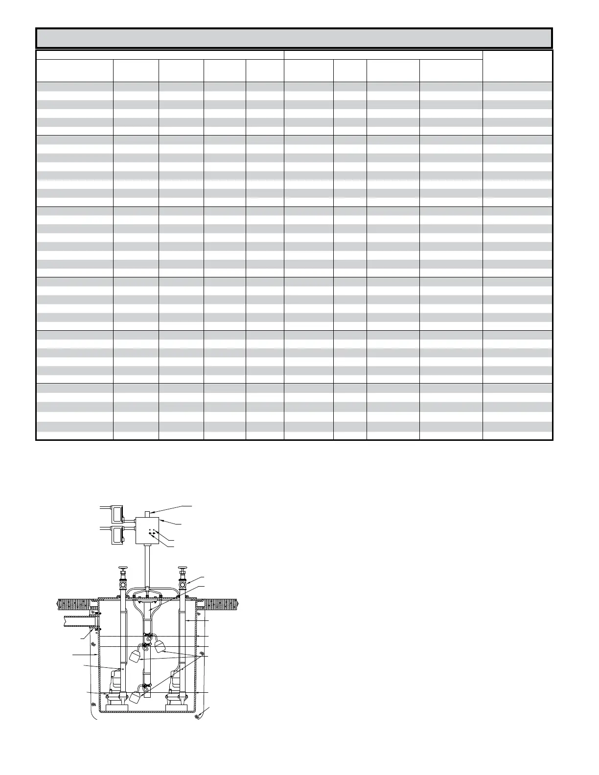
TYPICAL INSTALLATION USING DUPLEX CONTROL PANEL
SK484
GATE VALVE
FLOAT SUPPORT FABRICATED
FROM PVC OR S.S. PIPE
DN50 (2") OR DN80 (3")
DISCHARGE PIPE
ALARM LEVEL
(BOTH PUMPS ACTIVATED)
ON LEVEL
ZOELLER VARIABLE LEVEL
CONTROL SWITCH
OFF LEVEL
ZOELLER NONAUTOMATIC
SEWAGE PUMP
BASIN
INLET HUB
4" (102 mm)
OF GRAVEL
3/16” (5 mm)
VENT HOLE
TOGGLE SWITCHES
INDICATOR LAMPS
CONTROL PANEL
ELECTRICAL ALTERNATOR
ALARM LIGHT
 Loading...