4
© Copyright 2016 Zoeller
®
Co. All rights reserved.
INSTALLATION
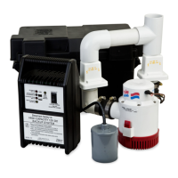
11. Mount DC charger to the wall. If more convenient, the charger may be
set on a nearby shelf or ledge. The charger should be located 3 or 4 ft.
above the sump. Then, remove protective screen from the front of the
charger.
12. Connect the leads from the control charger to the battery terminals.
Positive (+) lead to positive terminal and black neg. (-) lead to negative
battery terminal. Upon proper connection, test alarm will momentarily
sound. This indicates proper charger to battery connection.
Correct battery hook up is essential for operation of
the system. Use wing nuts supplied with battery and eyelet connectors
on battery wire leads. The positive terminal is the larger stud, 3/8"
diameter. The smaller stud, 5/16" diameter is the negative terminal.
Apply grease to the terminals to help prevent corrosion.
13. Connect the black lead from the pump to the negative (-) battery
terminal. Connect the white lead from the pump to the black lead
from the switch. This connection is made at the fuse installed on the
switch wire (see gure 3). Connect the white lead from the switch to the
positive (+) battery terminal.
14. Connect the green sensor wire to the sensor connector (gure 3).
15. Close battery box and secure cover. Carpeted or wood barrier between
the battery case and the oor is recommended.
16. Plug the charger's cord into charger and the 115V wall outlet. The primary
sump pump and the control box should be on separate circuits.
17. Reconnect power to primary sump pump.
18. Optional: A dongle may be used to input a name and number into the
charger for service information to the end user.
19. Optional: On the bottom of the charger there is a pair of dry contacts
to signal an auxiliary device of a low battery, high water and reverse
polarity alarm condition. This simple 2-wire connection is rated at a
maximum of 24V AC/DC and 0.5 amps. It can be used with an auto-
dialer (such as the Zoeller 10-2616), alarm or home security system.
Read the auxiliary equipment's documents for further instructions.
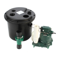
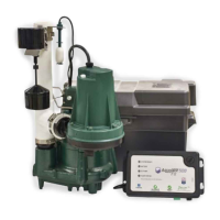
1. The preferred method of installation for backup pumps is shown in
Figures 1 and 2. The installation kit includes the necessary ttings and
one check valve for installing with the backup pump discharging into the
primary pump outlet pipe. An additional check valve is incorporated in the
discharge of the backup pump.
NOTE: Do not install in small spaces where the charger will not be
properly cooled.
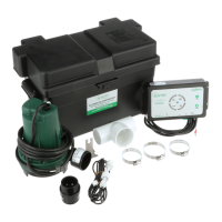
2. Remove all parts from shipping carton and make sure all parts are
included. Refer to checklist on page 3.
3. Select location for battery and control charger. Control charger must be
within 6' of a 115V wall outlet and within 6' of pump and basin. Connect to
a separate circuit, different than the primary pump.
4. If primary pump is installed, disconnect power.
NOTE: Discharge piping must be 1-1/2" SCH 40 PVC
5. Remove the discharge pipe from the pump and put to the side.
6. Solvent weld DC pump to tee at a 30 degree angle as shown in Figure 4.
7. Install in-line check valve into primary pump discharge.
8. Determine the position of the DC pump and measure between the in-
line check valve and tee. Use that measurement to cut discharge pipe.
Solvent weld that piece rst to the tee. Measure, cut & solvent weld any
remaining discharge piping above the tee. Finally, connect the discharge
pipe to the in-line check valve and tighten hose clamp. See Figure 4..
NOTE: Check oat operations to ensure the hose clamp screws do not
interfere with the oat operation of the primary pump.
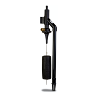
9. Assemble the oat assembly per gure 5.
10. Install the oat switch assembly bracket above the outlet tee using the
clamp provided (see gures 1 and 2). Make certain the clamp is tight on
the pipe to avoid slippage. Ensure that the “off” level of the oat is 1" min.
above the discharge tee of the DC backup pump (see gures 1 and 2).
Position pumps in the sump and move oat up and down, making sure of
free movement without interference from any obstructions inside the sump
or lid. The oat switch can be moved on the discharge pipe or the rubber
stops can be adjusted as necessary. Cut extra oat rod length below lower
oat stop to prevent debris from interfering with oat operation.
INITIAL START-UP AND OPERATION
1. Test the installation for leaks by running water into the sump allowing
for normal operation of the primary pump.
2. Check the control charger. The “red” power on light will be lit when the
unit is plugged into the 115V wall outlet. The charged/charging lights will
indicate the condition of the battery when the charger has AC power.
3. Disconnect primary pump before touching any component in the sump pit.
4. Lift oat switch. The DC backup pump will run and the alarm will sound.
Lower oat switch immediately after alarm has sounded. Pump is running
dry during initial check for several seconds.
Continuous
dry running may cause overheating and damage the pump seals. Upon
release of the oat switch, the pump will shut off. Press the reset button
to turn the alarm off.
5. Complete the nal testing of your installation by ensuring the primary pump
is still disconnected from the power. Then, unplug the charger from the
115V wall outlet. Run water into the sump until the DC backup pump
is activated by the oat switch. Check all connections for leaks.
NOTE: When running the primary pump, it is normal for a stream of
water to spray out of the 1/8" air relief hole.
6. Push alarm reset switch when pump is running. This will silence the alarm.
The pump will continue to run.
7. Reconnect the charger and your primary pump to the AC wall outlets. The
primary pump should come on and lower the water level in the sump
back to the normal operating level and shut off. Use the alarm reset
button to reset the high water light. Both primary and backup systems
are now ready for use.
8. The battery charged and charging LED’s will alternate during normal
charging operation.
NOTE: See page 7 for a description of charger functions.
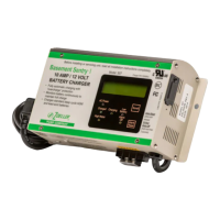
The DC controller is equipped with a 10 amp charger for maintaining the battery in a ready state and recharging the battery after use when AC power
is restored. Time for recharge depends upon the amount of power consumed by the pumping cycle during the AC power interruption. The pump may
go back to the ready run position in a very short period of time. A completely drained battery may require up to 24 hours for full recharge. If battery
does not charge properly, the LCD will display BATFAIL and the alarm will sound.
PERFORMANCE
Discharge: Feet of Head 5 10 14.5
Flow: Gal. per Min. 22 11 Shut-off Head
The DC pump performance with fully charged 12V battery
 Loading...