4
© Copyright 2009 Zoeller Co. All rights reserved.
Installation
moved on the discharge pipe or the rubber stops can be adjusted
as necessary. Cut extra fl oat rod length below lower fl oat stop to
prevent debris from interfering with fl oat operation.
12. If the old primary pump discharge piping is being replaced with
PVC piping, duplicate the old pipe dimensions and use the exist-
ing drainage connection. If the primary pump and backup pump
is a new installation, the drainage connection must be determined
and the discharge pipes fi tted accordingly. Solvent weld the up-
per portion of the discharge pipe into the PVC tee outlet (see
fi gures 1 and 2). Connect the discharge pipe into the drainage
connection. The pipe must be supported from above to ensure
adequate support for the pump assembly. Reinstall pumps in
sump pit with discharge back to its original position.
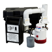
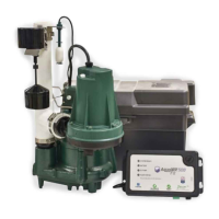
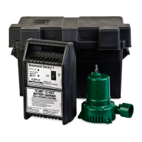
13. Install DC control charger (see fi gure 3) by using the wall bracket
and anchors provided. If more convenient, the control charger
may be set on a nearby shelf or ledge. The control charger
should be located 3 or 4 ft. above the sump. To reduce noise
from vibration, it is recommended that the charger be anchored
with the wall bracket provided.
14. Connect the leads from the control charger to the battery termi-
nals. Red pos. (+) lead to positive terminal and black neg. (-)
lead to negative battery terminal. Upon proper connection, test
alarm will sound. Press alarm reset to silence. This indicates
proper charger to battery connection.
Correct
battery hook up is essential for operation of the system. Use
wing nuts supplied with battery and eyelet connectors on battery
wire leads. The positive terminal is the larger stud, 3/8" diameter.
The smaller stud, 5/16" diameter is the negative terminal. Apply
grease to the terminals to help prevent corrosion.
15. Connect the black lead from the pump to the negative (-) battery
terminal. Connect the white or red lead from the pump to the
white lead from the switch. This connection is made at the fuse
installed on the switch wire (see fi gure 3). Connect the black lead
from the switch to the positive (+) battery terminal.
16. Connect the blue sensor wire to the sensor connector (fi gure 3).
17. Close battery box and secure cover with the safety closure strap
provided. Carpeted or wood barrier between the battery case
and the fl oor is recommended.
18. Plug the control power cord into the 115V wall outlet. The primary
sump pump and the control box should be on separate circuits.
19. Reconnect power to primary sump pump.
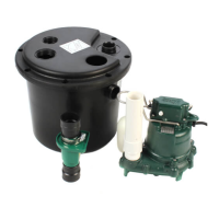
1. The preferred method of installation for backup pumps is shown in
fi gures 1 and 2. The installation kit includes the necessary fi ttings
and one check valve for installing with the backup pump discharg-
ing into the primary pump outlet pipe. An additional check valve is
incorporated in the discharge of the backup pump.
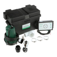
2. Remove all parts from shipping carton and make sure all parts are
included. Refer to checklist on page 3.
3. Select location for battery and control charger. Control charger
must be within 6' of a 115V wall outlet and within 6' of pump and
basin. Connect to a separate circuit, different than the primary
pump.
4. If primary pump is installed, disconnect power. If the primary pump
is a column pump with adjustable fl oat, and you are installing per
fi gure 2, check the “on” point and adjust to approximately 7 ½" from
bottom of pump (see fi gure 2). Mark the discharge pipe 7" above
the “on” point of the primary column pump or 7" above the top of
the primary submersible pump.
5. If existing discharge pipe is metal or fl exible tubing, it will need to
be replaced with SCH. 40 PVC piping. Use a male adapter for
connecting to the primary pump outlet.
6. Remove the discharge pipe and cut off at the mark determined in
step 4. Remove an additional 8" from the bottom portion.
7. Screw the discharge pipe into the primary pump outlet. Tighten
with strap wrench.
8. Assemble discharge fi ttings per fi gure 4. Note: Pump must be
glued into tee fi tting on a 30° angle to avoid air locking (see fi gure
4). Rotate pump while gluing until the line on the discharge is
facing up. Use a commercial grade of PVC cleaner and solvent
cement (not furnished with kit) on the socket joints.
9. Install the pump and discharge assembly per fi gure 1 or 2.
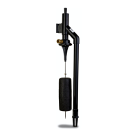
10. Assemble the fl oat assembly per fi gure 5.
11. Install the fl oat switch assembly bracket above the outlet tee using
the clamp provided (see fi gures 1 and 2). Make certain the clamp
is tight on the pipe to avoid slippage. Use electrical tape below
the clamp to help prevent the clamp from moving. Ensure that the
“off” level of the fl oat is 1" min. above the discharge tee of the DC
backup pump (see fi gures 1 and 2). Position pumps in the sump
and move fl oat up and down, making sure of free movement with-
out interference from any obstructions inside the sump or lid. Very
shallow sumps may require some adjustment to avoid overfi lling or
backing up of water into the sump inlet. The fl oat switch can be
Initial Start-Up and Operation
1. Test the installation for leaks by running water into the sump
allowing for normal operation of the pri mary pump.
2. Check the control charger. The “red” power on light will be lit when
the unit is plugged into the 115V wall outlet. The “yellow/green”
light will indicate the condition of the battery.
3. Disconnect primary pump before touching any component in the
sump pit.
4. Lift fl oat switch. The DC backup pump will run and the alarm will
sound. Lower fl oat switch immediately after pump has started
run ning. Pump is running dry during initial check out for several
seconds. Continuous dry run ning may cause
over heat ing and damage the pump seals. Upon release of the
fl oat switch, the pump will shut off. Press the reset button to turn
the alarm off.
5. Complete the fi nal testing of your installation by disconnecting the
power to the primary pump and the control charger by removing
the plugs from the 115V wall outlets. Run water into the sump
until the DC backup pump is activated by the fl oat switch. Check
all connections for leaks.
6. Push alarm reset switch when pump is running. This will silence
the alarm. The pump will continue to run.
7. Reconnect the control charger and your primary pump to the AC
wall outlets. The primary pump should come on and lower the
water level in the sump back to the normal operating level and
shut off. Both primary and backup systems are now ready for
use.
8. The battery charged and charging LED’s will alternate during
normal charging operation.
 Loading...