V4™
Installation/User Guide
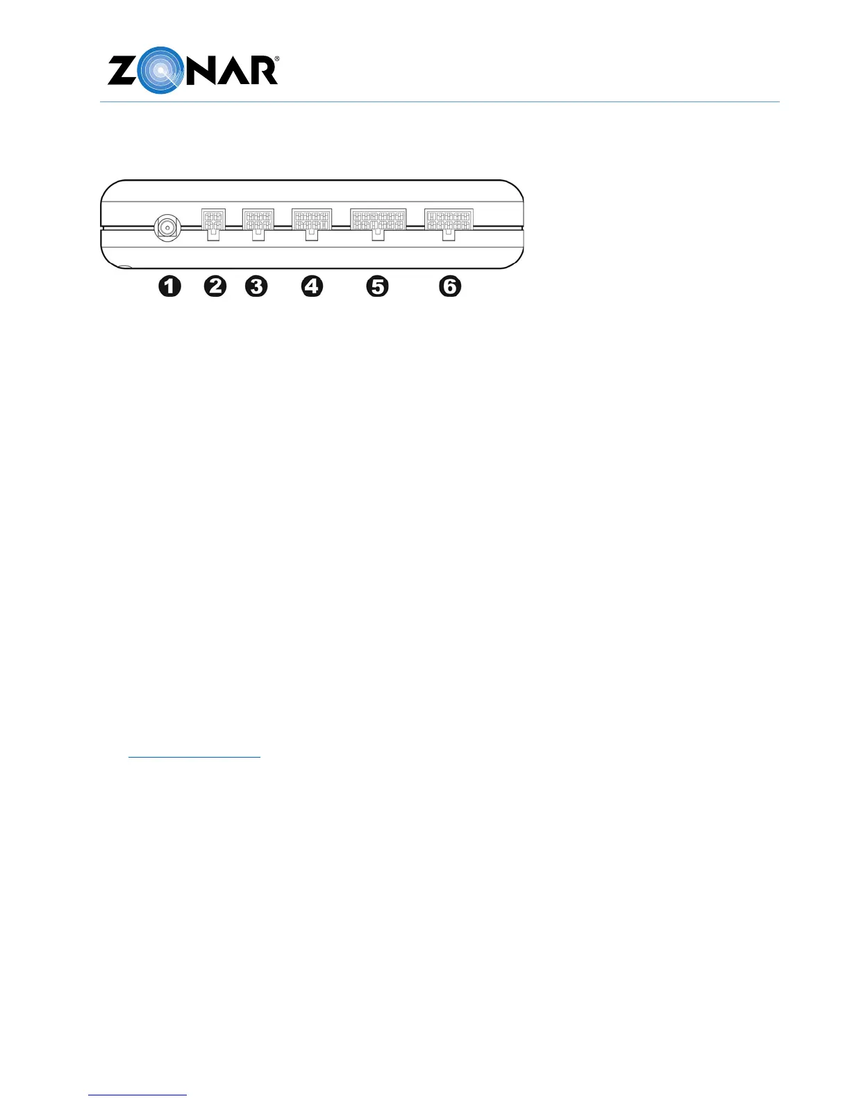
V4 Pin Configuration
1. External GPS antenna (Optional)
2. 4 Pin Power Input (Disconnect first, Reconnect last)
3. 6 Pin Accessory Port: Z Pass™/Operator ID
4. 8 Pin for 2010/2020/Connect Dock
5. 12 Pin Discrete Input (Optional)
6. 10 Pin ECM input (SAE J1708/J1939 & OBDII equipped vehicles)
Power/Data Cables
The V4 has the following primary cables for connecting to the vehicle electrical and data
system:
• 4 Pin, 3 Wire Power Cable (Part# 10007)
• Light Duty (LD) Power Cable (Part# 81008 with LD Breakout Part# 80999)
• 9 Pin Diagnostic 500K Cable (Part# 81523) with optional 6-9 pin adapter (Part# 81632)
• 2 Pin Deutsch 500K Cable (Part# 81517)
Additionally, there is a fifth uncommon cable specifically used to wire around battery
disconnect systems: 4 Pin, 4 Wire power cable (Part# 10030).
See General Guidelines before you begin. Do not connect to the 4 pin power input until all
other V4 cables have been connected.