V4™
Installation/User Guide
4 Pin Testing and Cable Management
The 4 pin power cable is used on Non-J1708/J1939 and non-OBDII installs. It is also used on
J1708/J1939 installs with switched power issues (as indicated by flashing “Status” LED with
engine running). See General Guidelines and the following requirements.
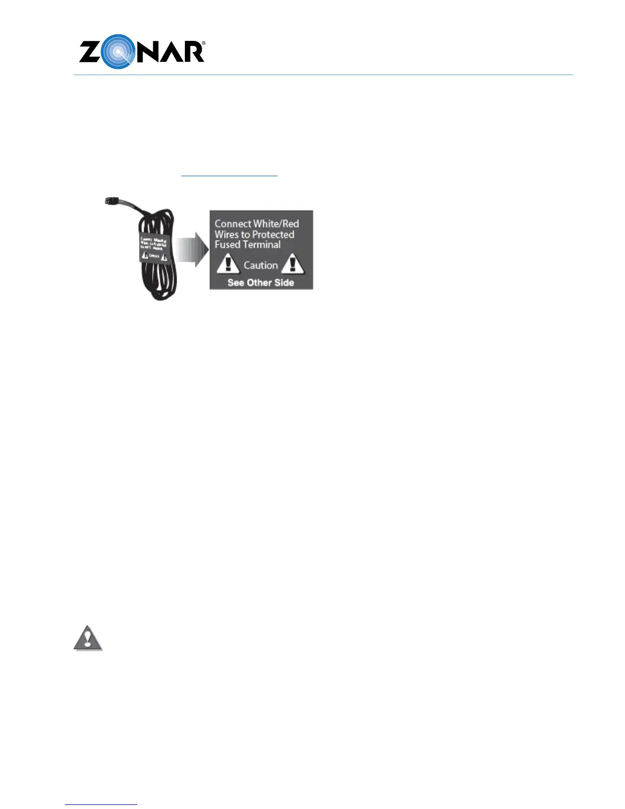
1. All power leads must be connected to the vehicles protected circuitry (for example, the
fuse panel and circuit breaker panel protected circuits). Never electrically connect Zonar
equipment to unprotected circuits (for example, directly to the battery).
2. All power leads (red and white) must be protected with a 3 to 5 amp fuse and inline fuse
holder (included) for optimal system protection.
3. Electrical fuses should be installed as close as possible to the source of power.
4. For vehicles equipped with “noise kill” switches (late model school buses) – Do not wire
any Zonar equipment to the “noise kill” circuitry.
Power Bundle Wiring – 4 Pin
• Red – Constant DC (+8 VDC to +32 VDC), dependent on system type
• Black – Battery Ground must be less than 1 ohm (measure from 4 Pin connector to
chassis attachment point)
• Green - Chassis ground (Cable P/N 10030 only).
• White - Switched Power
o Engine running (+8 VDC to +32 VDC)
o Engine not running (0 VDC)
o Engine not running (key position ACC or Accessory Mode) (0 VDC)
The white wire must be connected to a power source that is active only when the
engine is running or the system will not track idle time properly.
Note: Please contact the vehicle manufacturer for any specific electrical questions.