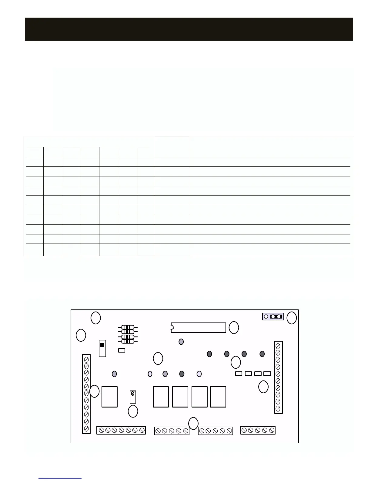
Y1 G W2
PWR
DPR1 DPR2 DPR3 DPR4
ON
-
R
E
L
C
O/B
+
1
2
3
3
4
4
TR1
TR2
2
1
DIGITRACT 4-2 HP TWO STAGE 210806
BO
JPR1
Vx.x
R72
O/B R Y G C
STAT 4
O/B R Y G C
STAT 3
O/B R Y G C
STAT 2
STAT 1
O/BR Y G CEL
Y2O/B
R8
R10
R9
R5
Y2
Y1
G
W2
A
B
C
D
EF
G
H
I
J
STATUS LEDs
COMPONENTS DTHP4-2
9
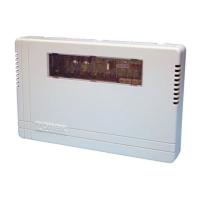
SYSTEM CONTROLLER – HEAT PUMP DTHP4-2
O/B Reversing valve LED, yellow. On when the reversing valve is energized.
Y1 Compressor LED, yellow. On when the first compressor stage is energized.
Y2 Compressor LED, yellow. On when the second compressor stage is energized.
G Indoor blower LED, green. On when the indoor blower is energized by the DTHP4-2 Controller.
W2 Auxiliary heat LED, red. On when the auxiliary heat is energized.
PWR Power LED, orange. On when DTHP4-2 is powered. Flashing during capacity control cutout.
DPR Damper status LED, red. One per damper. On when damper is closed.
STATUS LEDs
O/B Y1 Y2 G W2 PWR DPR MODE FUNCTION
OFF OFF OFF OFF OFF OFF OFF Off Power off.
OFF OFF OFF OFF OFF ON OFF On Power on, blower off, all zones satisfied.
OFF OFF OFF ON OFF ON 0 Vent Blower on, compressor(s) off, all zone dampers open.
OFF OFF OFF ON OFF ON 1 Purge Blower off, compressor(s) off. Dampers with LED on are closed.
A ON OFF ON OFF ON 1 Y1 Cool 1st stage cool, blower on. Dampers with LED on are closed.
A ON ON ON OFF ON 1 Y2 Cool 2nd stage cool, blower on. Dampers with LED on are closed.
B ON ON ON C ON 1 Y1 Heat 1st stage heat, blower on. Dampers with LED on are closed.
B ON ON ON C ON 1 Y2 Heat 2nd stage heat, blower on. Dampers with LED on are closed.
OFF OFF OFF ON ON ON 0 Em. Heat Auxiliary and emergency heat on.
OFF OFF OFF ON OFF FL 1 Cap Cut out Blower on, all compressors off. Dampers with LED on are closed.
FL = Flashing A = On when reversing valve jumper is in O position B = On when reversing valve jumper is in B position
C = On when auxiliary heat is energized 1 = One or more damper LEDs on 0 = All damper LEDs are off